Eureka AIR delivers breakthrough ideas for toughest innovation challenges, trusted by R&D personnel around the world.

Communications system and method with multilevel connection identification

Inactive Publication Date: 2006-10-10
META PLATFORMS TECH LLC
View PDF25 Cites 55 Cited by
  • Summary
  • Abstract
  • Description
  • Claims
  • Application Information

AI Technical Summary

Benefits of technology

[0011]One embodiment of the present invention includes a shared communications bus for providing flexible communication capability between electronic sub-systems. One embodiment includes a protocol that allows for identification of data transmissions at different levels of detail as required by a particular sub-system without additional knowledge being designed into the sub-system.

Problems solved by technology

Electronic computing and communications systems continue to include greater numbers of features and to increase in complexity.
At the same time, electronic computing and communications systems decrease in physical size and cost per function.
In some systems, one or several of these extremely complex chips must communicate with each other and with other system components.
Significant new challenges arise in the integration, verification and testing of such systems because efficient communication must take place between sub-systems on a single complex chip as well as between chips on a system board.
One challenge in the integration, verification and testing of modern electronic systems stems from the fact that modern electronic systems in many application areas have functionality, cost and form-factor requirements that mandate the sharing of resources, such as memory, among multiple functional blocks, where functional blocks can be any entity that interfaces to a communication system.
Customized interfaces, however, are by their nature inflexible.
One disadvantage of computer buses is that each sub-system or component connected to the bus is constrained to use the protocol of the bus.
In some cases, this limits the performance of the sub-system.
For example, a sub-system may be capable of handling multiple transaction streams simultaneously, but the bus protocol is not capable of fully supporting concurrent operations.
Conventionally, such identification is limited to a non-configurable hardware identifier that is generated by a particular sub-system or component.
Current bus systems provide limited capability to preserve order in one transaction stream by supporting “split transactions” in which data from one transaction may be interleaved with data from another transaction in the same stream.
Current bus systems do not support true concurrency of operations for a sub-system that can process multiple streams of transactions over a single interconnect, such as a memory controller that handles access to a single dynamic random access memory (DRAM) for several clients of the DRAM.
Current communication systems do not provide for such information to be transmitted with data without placing an additional burden on the sub-system to adapt to the existing protocol.
This makes sub-systems more expensive and less flexible in the event the sub-system is later required to communicate with new sub-systems or components.
Existing communication approaches thus do not meet the requirements of today's large, complex electronics systems.

Method used


Image

  • Communications system and method with multilevel connection identification
  • Communications system and method with multilevel connection identification
  • Communications system and method with multilevel connection identification

Examples


Embodiment Construction

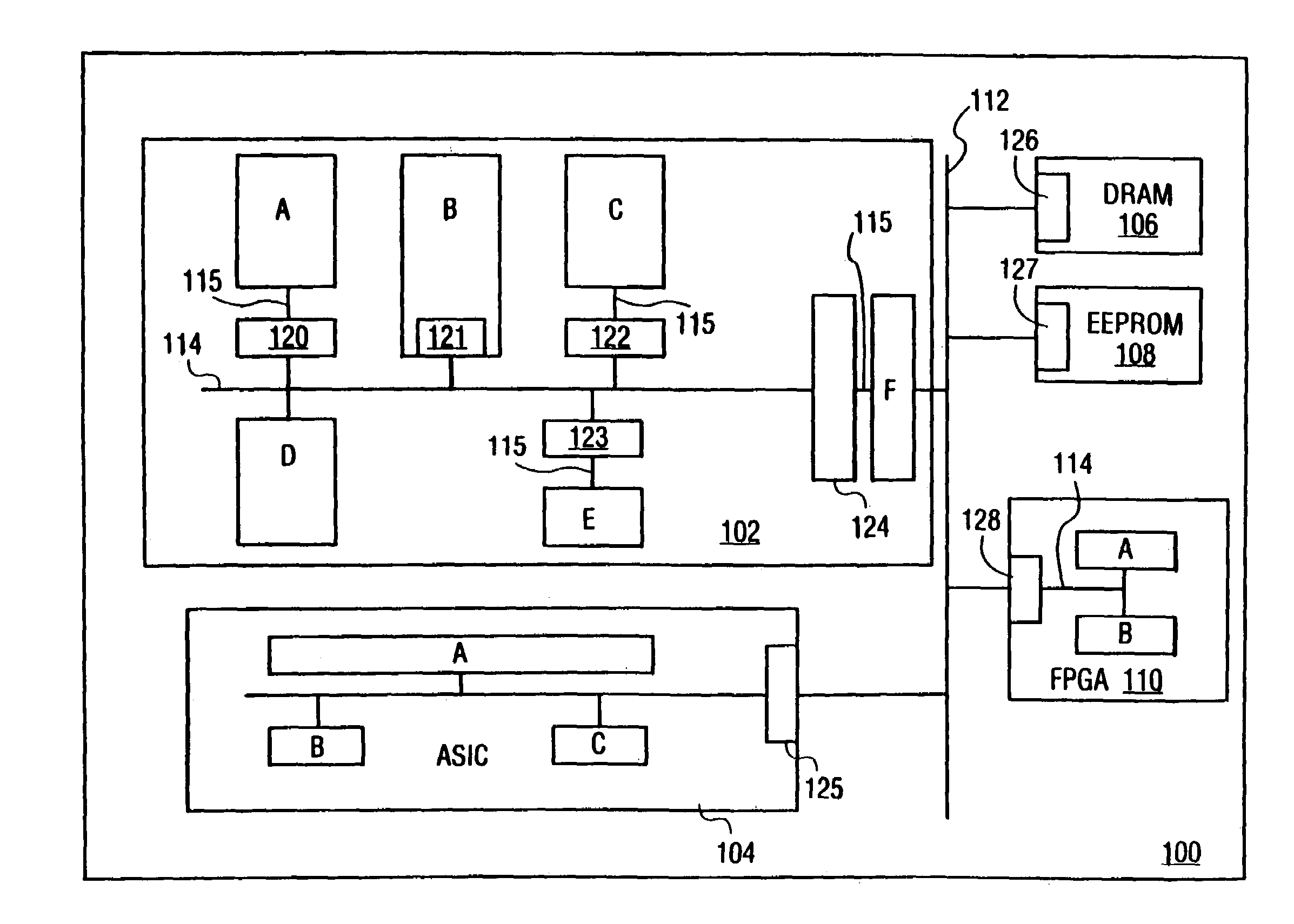
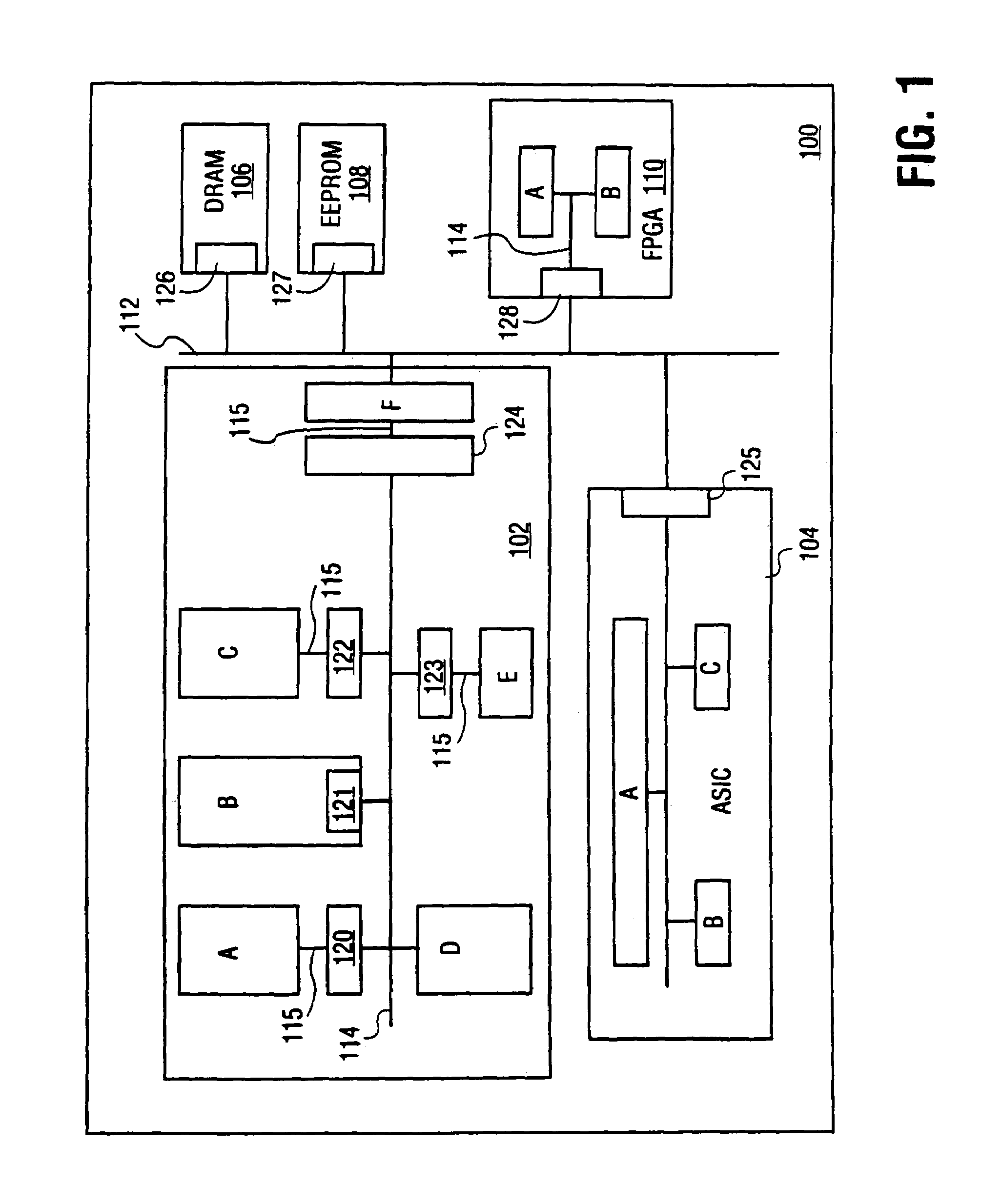
[0027]The present invention is a communications system and method for allowing multiple functional blocks or sub-systems of a complex electronics system to communicate with each other through a shared communications resource, such as a shared communications bus. In one embodiment, a communications protocol allows multiple functional block on a single semiconductor device to communicate to each other. In another embodiment, the communications protocol may be used to allow multiple functional blocks on different semiconductor devices to communicate to each other through a shared off-chip communications resource, such as a bus.

[0028]In one embodiment, the present invention is a pipelined communications bus with separate command, address, and data wires. Alternative embodiments include a pipelined communications bus with multiplexed address, data, and control signals. The former embodiment offers higher performance and simpler control than the latter embodiment at the expense of extra w...


PUM


Abstract

A communication system. One embodiment includes at least two functional blocks, wherein an first functional block communicates with a second functional block by establishing a connection, wherein a connection is a logical state in which data may pass between the first functional block and the second functional block. One embodiment includes a bus coupled to each of the functional blocks and configured to carry a plurality of signals. The plurality of signals includes a connection identifier that indicates a particular connection that a data transfer is part of, and a thread identifier that indicates a transaction stream that the data transfer is part of.

Description

RELATED APPLICATIONS[0001]This application is a continuation application of U.S. application Ser. No. 09 / 721,044 filed Nov. 21, 2000 now U.S. Pat. No. 6,725,313, which is a continuation of U.S. application Ser. No. 09 / 191,291, now U.S. Pat. No. 6,182,183 filed Nov. 13, 1998.FIELD OF THE INVENTION[0002]The present invention relates to a communication system to couple computing sub-systems.BACKGROUND OF THE INVENTION[0003]Electronic computing and communications systems continue to include greater numbers of features and to increase in complexity. At the same time, electronic computing and communications systems decrease in physical size and cost per function. Rapid advances in semiconductor technology such as four-layer deep-sub-micron complimentary metal-oxide semiconductor (CMOS) technology, have enabled true “system-on-a-chip” designs. These complex designs may incorporate, for example, one or more processor cores, a digital signal processing (DSP) core, several communications inte...

Claims


Application Information

Patent Timeline
IPC IPC(8): G06F13/42G06F13/00G06F13/36G06F13/14G06F13/38H04L12/00H04L12/403
CPCG06F13/385G06F13/4243H04L12/403H04L12/66
Inventor WINGARD, DREW ERICROSSEEL, GEERT-PAULTOMLINSON, JAY S.ROBINSON, LISA A.
Owner META PLATFORMS TECH LLC
Why Eureka
Eureka Blog
Learn More