
High-temperature inspection device and cooling apparatus therefor

a technology of high-temperature inspection and cooling apparatus, which is applied in the field of visual inspection equipment, can solve the problems of high temperature resistance of electronic borescope systems and video inspection equipment associated therewith, and high cost and time-consuming process, and achieve the effect of reducing the length of the cooling down time and avoiding the effect of expensive and long cooling down tim

Active Publication Date: 2006-10-17
SIEMENS ENERGY INC
View PDF3 Cites 33 Cited by
  • Summary
  • Abstract
  • Description
  • Claims
  • Application Information

AI Technical Summary

Benefits of technology

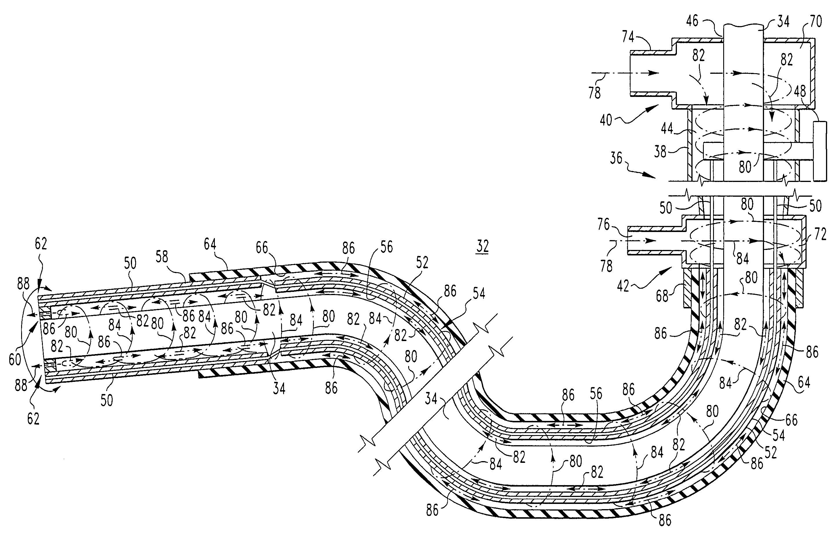
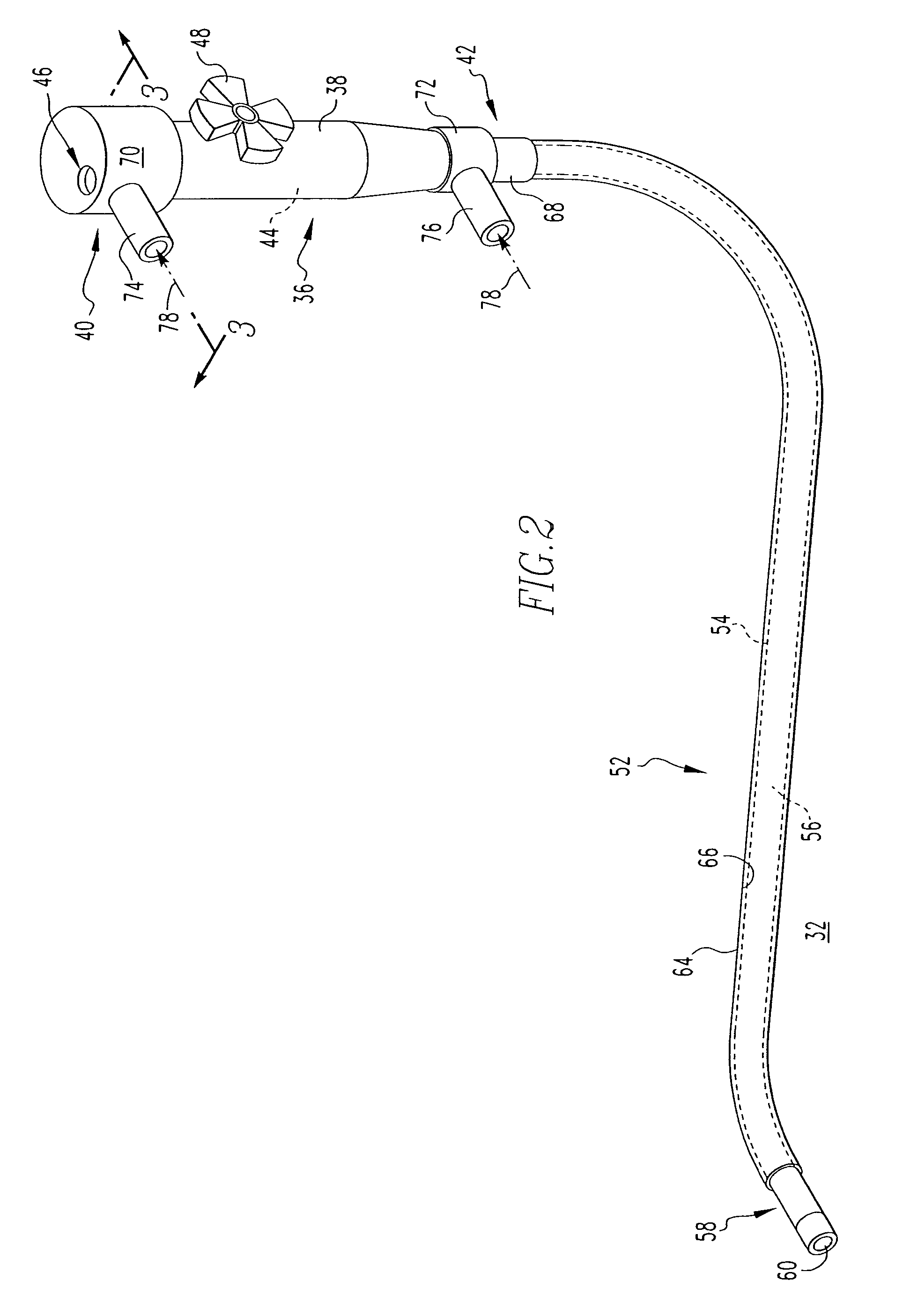
"The present invention is a high-temperature inspection device that allows for hot visual inspection of internal combustion turbine components immediately after shutdown and as soon as the turbine's inspection ports are opened. The device includes an articulating guide tube with a control portion, an elongated flexible portion, and an articulating section. A thermal protective sleeve surrounds the elongated flexible portion of the articulating guide tube. A cooling apparatus is used with the inspection probe, which includes an articulating guide tube, a thermal protective sleeve, an inlet, at least one vortex cooler, and an exhaust vent. The cooling apparatus uses a compressed fluid, such as compressed air, and a vortex cooler to cool the inspection probe and the turbine component being monitored. The cooling apparatus allows for full-way articulation and 360° viewing through the video borescope. The method involves inserting the video borescope into the cooling apparatus, supplying compressed air, and controlling the video borescope to conduct a visual inspection."

Problems solved by technology

Such prior art electronic borescope systems and the video inspection equipment associated therewith cannot withstand high temperatures.
This is an expensive and time-consuming process.

Method used


Image

  • High-temperature inspection device and cooling apparatus therefor
  • High-temperature inspection device and cooling apparatus therefor
  • High-temperature inspection device and cooling apparatus therefor

Examples


Embodiment Construction

[0026]The invention will be described as applied to the inspection of internal combustion turbine components, although it will become apparent that it could also be applied to inspect other types of power industry equipment, and to other applications (e.g., without limitation, automotive; aviation; surveillance; bomb squad).

[0027]As applied herein, “full-way” articulation refers to a video borescope inspection system that allows 360° viewing of, for example, combustion turbine components that exist in areas that require traveling around, through, or near other components.

[0028]As applied herein, “vortex cooler” refers to a vortex generating tube variously known as the “Ranque vortex tube,” the “Hilsch tube,” the “Ranque-Hilsch tube” and “Maxwell's Demon.” A vortex cooler has no moving parts. Compressed air is supplied to an internal counter bore through tangential inlet nozzles. The nozzles turn the compressed air into a vortex or spinning airstream that passes down the tube in the ...


PUM


Abstract

An inspection system includes a cooling apparatus for conducting visual inspections within operating temperature environments, such as, for example, the interior of a combustion turbine shortly after shut down. The cooling apparatus provides cooling for an inspection probe such as a video borescope. The cooling apparatus includes an articulating guide tube having a control portion, an elongate flexible portion and an articulating section. The video borescope is inserted down through the articulating guide tube. A thermal protective sleeve surrounds and thermally insulates a portion of the articulating guide tube. Vortex coolers circulate cooled, compressed air within the cooling apparatus, thereby maintaining a cool video borescope operating temperature.

Description

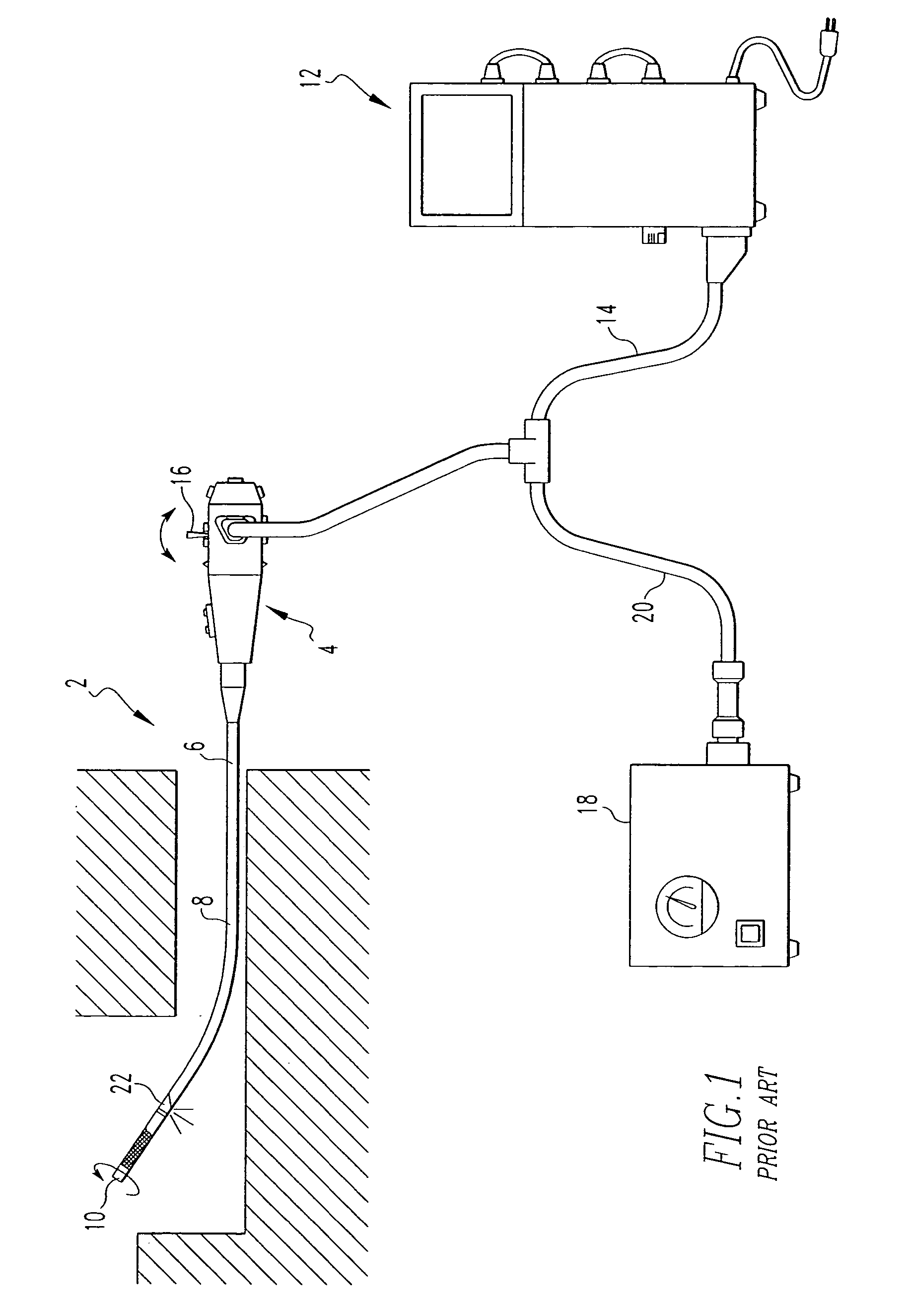
CROSS-REFERENCE TO RELATED APPLICATION[0001]This application claims priority under 35 USC § 119(e) to Provisional Application Ser. No. 60 / 466,478, filed on Apr. 30, 2003, entitled “High-Temperature Inspection Device,” explicitly incorporated herein by reference.BACKGROUND OF THE INVENTION[0002]1. Field of the Invention[0003]The present invention relates generally to visual inspection equipment and, more particularly, to a high-temperature inspection device employing a cooling apparatus, which enables continuous inspecting operations within high-temperature environments for extended periods of time. The invention also relates to cooling apparatus for high-temperature inspection devices.[0004]2. Background Information[0005]Inaccessible or confined areas such as, for example, the internal parts of power industry components (e.g., without limitation, combustors; compressors; turbines; power generation tubes), often require routine inspection to maintain safe operating conditions, to det...

Claims


Application Information

Patent Timeline
Patent Type & Authority Patents(United States)
IPC IPC(8): F25B9/02A61B1/04A61B18/18F23N5/08F23N5/24F25B9/04F27D19/00F27D21/02
CPCF23N5/08F23N5/24F25B9/04F27D19/00F27D21/02F23N2029/18F27D2021/026F23N2229/18
Inventor HATCHER, CLIFFORD
Owner SIEMENS ENERGY INC
Learn More