Diesel engine oil dilution managing device

a technology of managing device and diesel engine oil, which is applied in the direction of lubricating the crankcase compression engine, electric control, instruments, etc., can solve the problems of engine oil dilution by the fuel, increased amount of engine oil carried away by blow-by gas, and worsening of exhaust emissions, so as to prevent the degradation of exhaust emissions and

Inactive Publication Date: 2006-10-17
NISSAN MOTOR CO LTD
View PDF7 Cites 13 Cited by
  • Summary
  • Abstract
  • Description
  • Claims
  • Application Information

AI Technical Summary

Benefits of technology

[0011]One object of the present invention is to detect whether the engine oil in a diesel engine, which is configured to recirculate blow-by gas to the cylinder, is diluted with fuel and to prevent the degradation of exhaust emissions and the occurrence of knocking that can result from dilution of the engine oil by fuel.

Problems solved by technology

The fuel that sticks to the wall surface of the cylinder is mixed with the engine oil which results in dilution of the engine oil by the fuel.
On the other hand, since the mixing of the fuel into the engine oil raises the engine oil level in the oil pan, the amount of engine oil carried away by the blow-by gas increases.
In a diesel engine, if blow-by gas containing a large amount of unburned fuel is recirculated into the cylinder, combustion of the unburned fuel will occur before fuel is injected from the injector, possibly causing exhaust emissions to worsen and knocking to occur.
However, the conditions that exist in the cylinder before the fuel is injected are not monitored in such conventional diesel engine.
Furthermore, the above mentioned reference does not disclose an arrangement for detecting dilution of the engine oil by fuel.

Method used


Image

  • Diesel engine oil dilution managing device
  • Diesel engine oil dilution managing device
  • Diesel engine oil dilution managing device

Examples


second embodiment

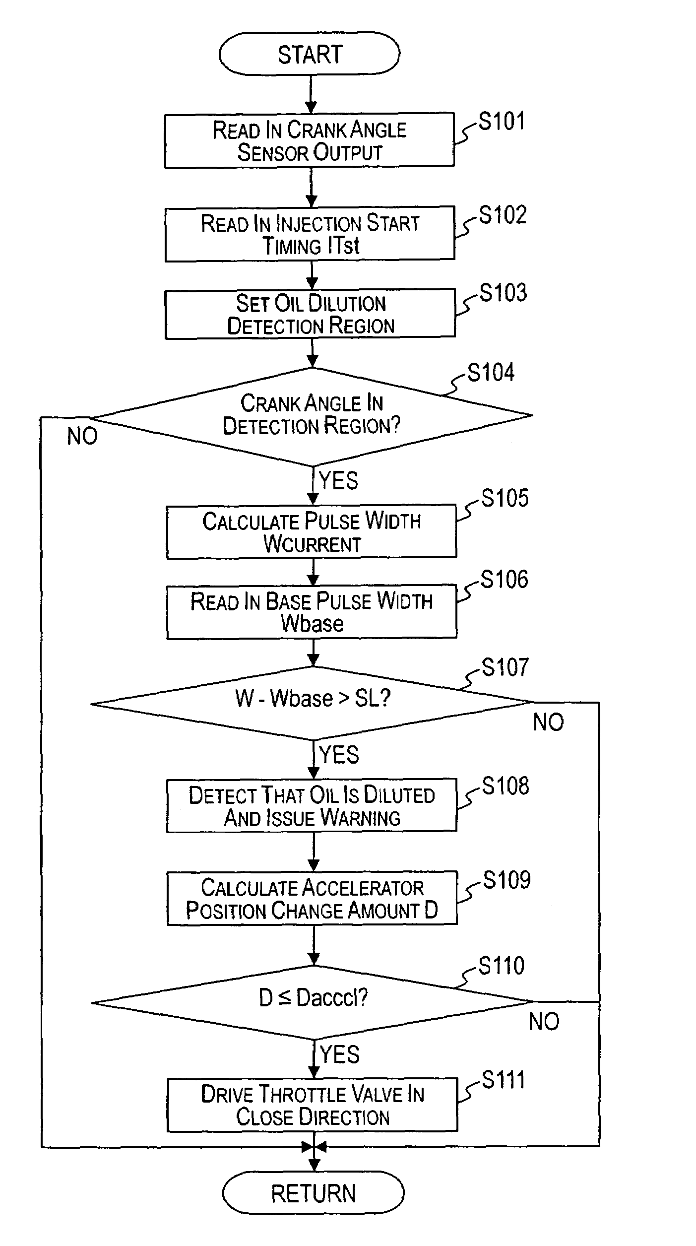
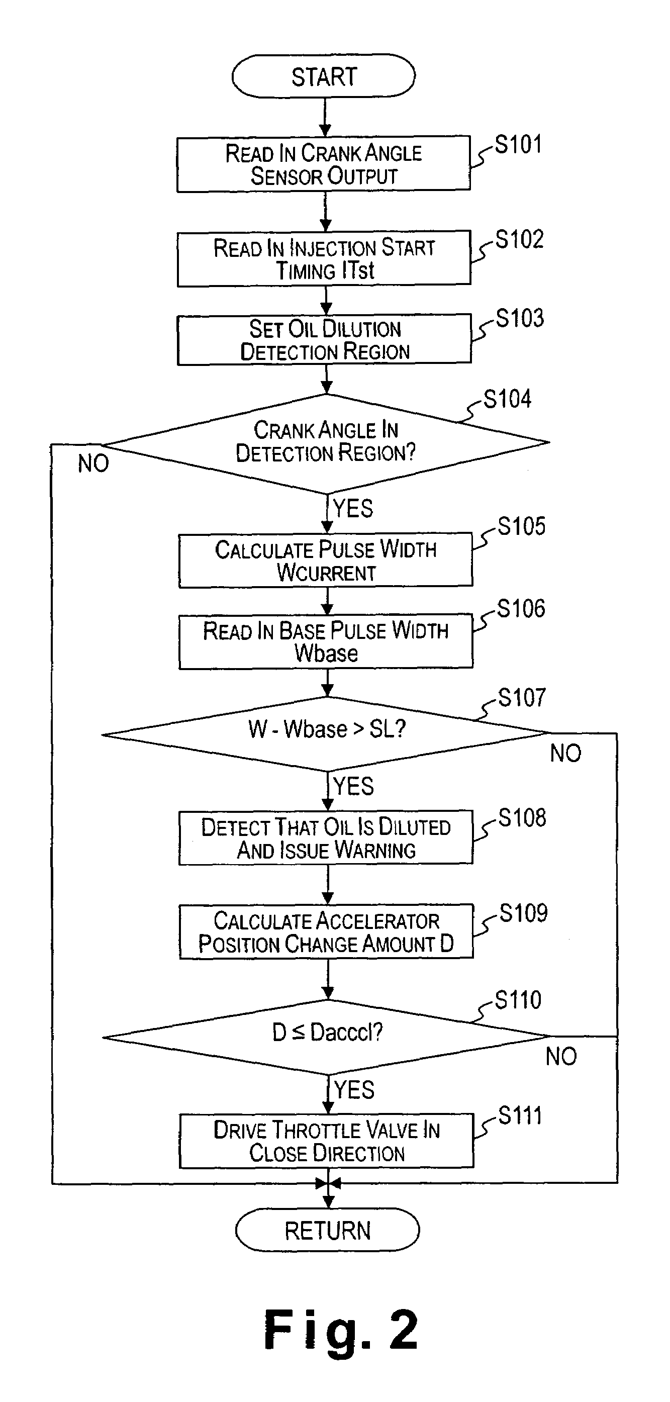
[0052]Referring now to FIGS. 6 and 7, a diesel engine oil dilution managing (detecting) device in accordance with a second embodiment will now be explained. In view of the similarity between the first and second embodiments, the parts of the second embodiment that are identical to the parts of the first embodiment will be given the same reference numerals as the parts of the first embodiment. Moreover, the descriptions of the parts of the second embodiment that are identical to the parts of the first embodiment may be omitted for the sake of brevity.

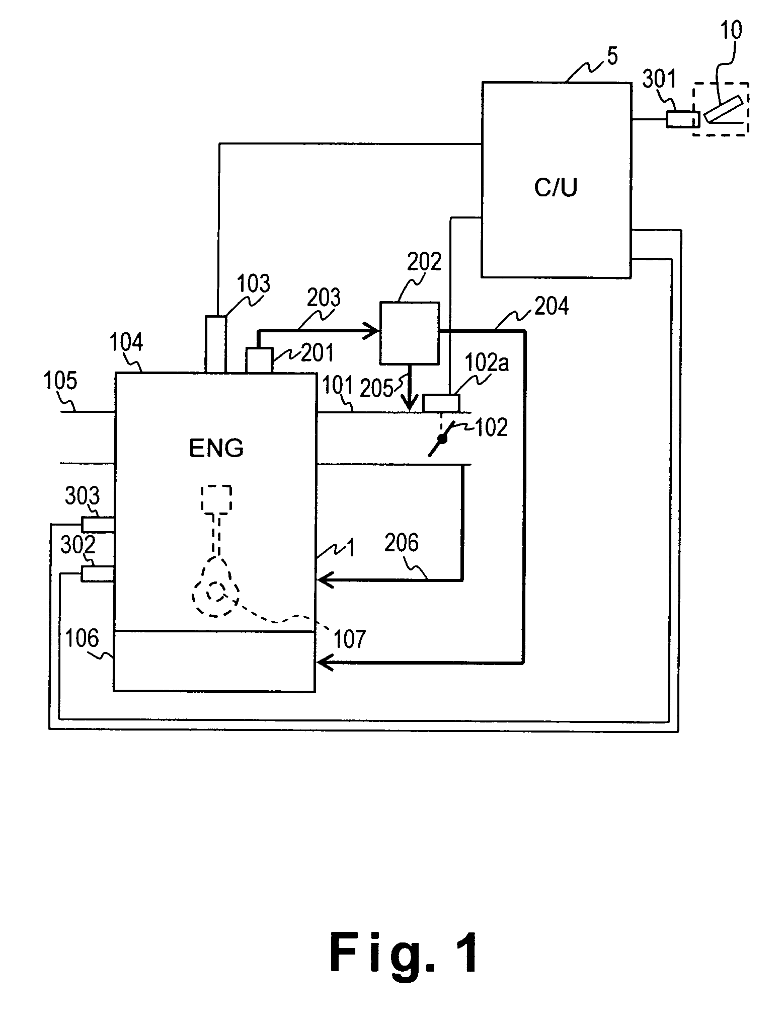
[0053]The diesel engine oil dilution managing device of the second embodiment is basically identical to the first embodiment, except for the control routine for detecting the oil dilution. In other words, the oil dilution managing device of the second embodiment can be applied to the diesel engine 1 in the first embodiment as shown in FIG. 1. More specifically, the second embodiment of the present invention defers from the first embodime...


PUM


Abstract

A diesel engine oil dilution managing device is configured to act as an oil dilution detecting device to determine if a premature combustion occurred before fuel injection by an injector based on an engine parameter that correlates with an occurrence of the premature combustion, such as an amount of time required for the crankshaft to rotate per unit crank angle or a rotational speed change rate of the crankshaft. Moreover, the diesel engine oil dilution managing device can have an engine output control section that is configured to suppress the production of output power by the engine when it is determined that the premature combustion occurred before the fuel injection by, for example, driving a throttle valve in a close direction.

Description

CROSS-REFERENCE TO RELATED APPLICATIONS[0001]This application claims priority to Japanese Patent Application No. 2004-166648. The entire disclosure of Japanese Patent Application No. 2004-166648 is hereby incorporated herein by reference.BACKGROUND OF THE INVENTION[0002]1. Field of the Invention[0003]The present invention relates to a diesel engine oil dilution managing device for a diesel engine that detects dilution of the engine oil by fuel. More specifically, the present invention relates to a technology utilized in a diesel engine, which is configured and arranged to recirculate blow-by gas to the cylinders, to detect dilution of the engine oil by fuel and to prevent unintended acceleration (i.e., unintended by the driver) resulting from the dilution of the oil.[0004]2. Background Information[0005]In a conventional diesel engine, blow-by gas that leaks from the combustion chamber through the piston rings is directed to an oil separator, which liquefies the engine oil in the blo...

Claims


Application Information

Patent Timeline
Patent Type & Authority Patents(United States)
IPC IPC(8): F01M3/04F01M3/00F01M1/00F01M11/10F01M13/00F01M13/04F02B3/00F02D17/00F02D41/00F02D41/04F02D41/22F02D41/38F02D41/40F02D45/00G01M99/00
CPCF02D41/0027F02D41/22F01M13/00F01M13/04F02D41/403F02D41/405F02D2250/11
Inventor YOKOYAMA, JIN
Owner NISSAN MOTOR CO LTD
Why Eureka
Try Eureka