
Magnetic tape cassettes, tape reels for use therewith, resinous leaf springs, and a process for producing them

a technology of tape cassettes and reels, applied in the field of magnetic tape cassettes, can solve the problems of reducing affecting the service life of reel retaining springs, and having their own problems, so as to reduce the impact of waste, reduce the impact of environment, and facilitate assembly

Inactive Publication Date: 2006-10-17
FUJIFILM HLDG CORP +1
View PDF18 Cites 4 Cited by
  • Summary
  • Abstract
  • Description
  • Claims
  • Application Information

AI Technical Summary

Benefits of technology

[0046]Thus, one of the principal objects of the invention is to provide a magnetic tape cassette that is free from the problems of the prior art, that permits tape reels in a cassette case to be urged by means of a member which is simple in structure and can be easily fitted and removed, and that is advantageous for assorted collection of constituent materials, particularly for assorted collection of resin materials and selective collection of resin materials as separate from metal materials.
[0083]an urging means that applies urging force between an area of contact and the engage-and-stop members on the upper flange that have come into contact and engagement with the engage-and-stop lugs on the lower flange, thereby causing the engage-and-stop members to be elastically secured to the engage-and-stop lugs,

Problems solved by technology

With the recent growing concern over environmental problems, increasing attention is drawn to the possibility that the increase in various kinds of wastes including those of metals, resins (plastics) and composite materials may cause adverse effects on the environment.
The prior art products described above have their own problems.
Hence, when disassembling a conventional magnetic tape cassette after use and separating the components according to whether they are made of resin or metal or resinous parts are separated by resin type with a view to collecting the components by material, the reel retaining spring cannot be dislodged easily; needless to say, it cannot be removed unless the cassette case is disassembled and dislodging the reel retaining spring from the inner surface of the upper half is a complex operation that involves considerable labor and cost.
It is not very difficult to bring the two lugs out of engagement but, on the other hand, assembling the metallic spring unit 500 is a complicated work, causing various problems such as the potential breaking of the resinous projection 504a and resin chipping of the bottom of the slot 504 due to the sliding of the slider 500c.
Once the upper and lower flanges are fastened together by ultrasonic or thermal welding to make a tape reel, considerable difficulty is involved in disassembling it safely and assorting the individual components by material.
However, the surface of the upper flange which is to be welded to the lower flange and the reference plane of the lower flange are not usually molded by a single die but molded by two dies, one fixed and the other movable, and on account of various factors including the precision in mating of dies, its thermal deformation and the pressure of molten plastic being injected, the mating position of dies is inevitably subject to change and it has been difficult to secure adequate precision in assembly of the upper flange.
However, the upper half which combines with the lower half to make the cassette case must have sufficiently high rigidity and strength that it can not only be loaded into or unloaded from the record / reproduce apparatus but also withstand transport.
Hence, in order to determine the thickness of the spring that assures an appropriate spring load for preventing unwanted rotation of magnetic tape, a lot of samples must be prepared at different thicknesses and it is necessary to check for the appropriate thickness of spring; on top of this, variations in thickness must be controlled but this adds to the complexity in manufacturing procedures.

Method used


Image

  • Magnetic tape cassettes, tape reels for use therewith, resinous leaf springs, and a process for producing them
  • Magnetic tape cassettes, tape reels for use therewith, resinous leaf springs, and a process for producing them
  • Magnetic tape cassettes, tape reels for use therewith, resinous leaf springs, and a process for producing them

Examples


Embodiment Construction

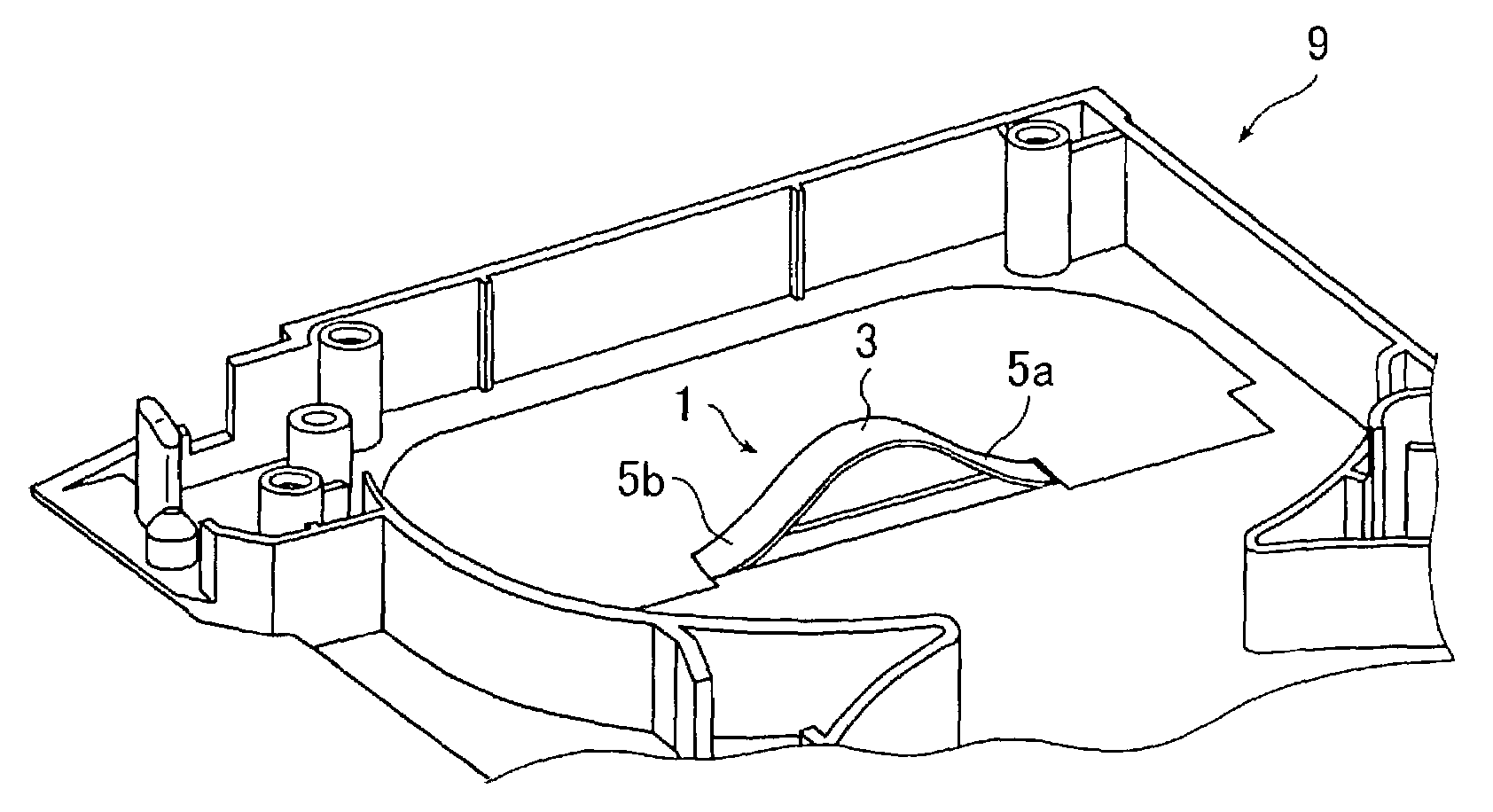
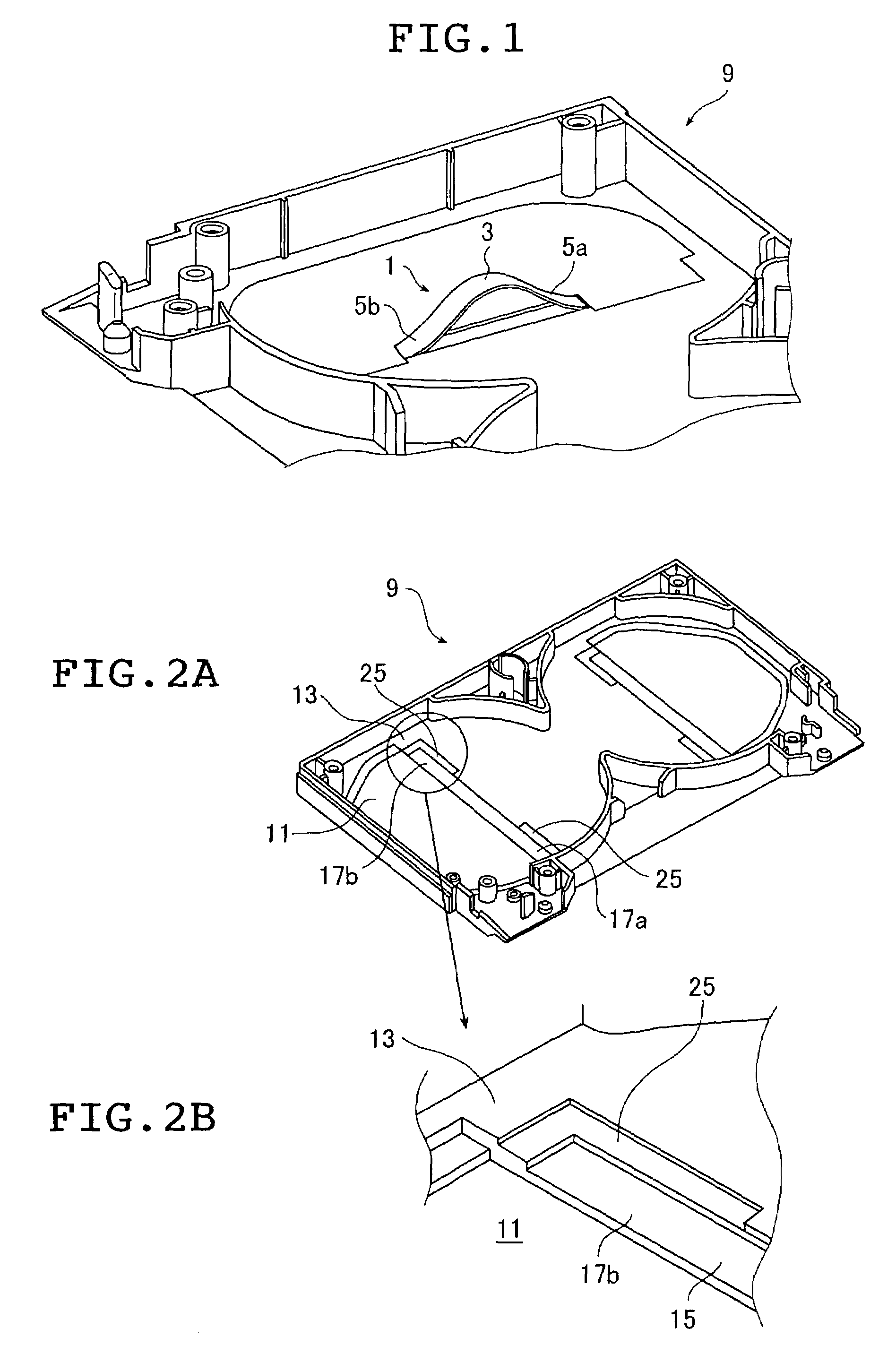
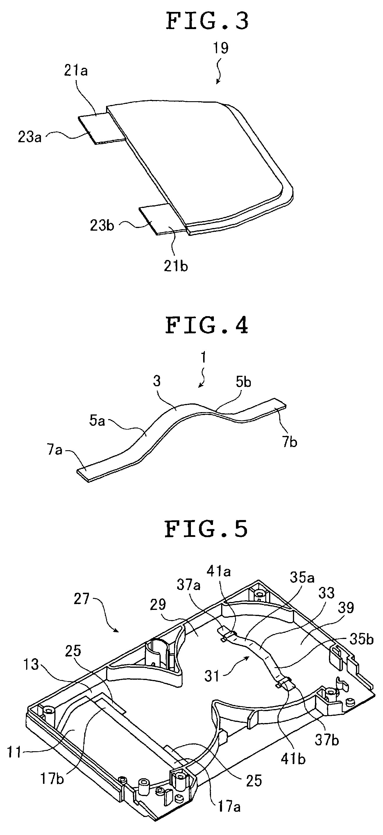
[0183]The magnetic tape cassettes of the invention, the tape reels for use with them, as well as the resinous leaf spring and the process for producing it are described below in detail with reference to the preferred embodiments shown in FIGS. 1–52 in the accompanying drawings.

[0184]On the pages that follow, the magnetic tape cassette of the invention (which is hereunder sometimes referred to simply as the cassette) will be described in detail. In the following description, the term “upper” refers to the side on which the upper half is located, the term “lower” refers to the side on which the lower half is located, the term “front” refers to the side on which the front cover is located, and the term “rear” refers to the opposite side.

[0185]The concept of the invention is applicable to magnetic tape cassettes having magnetic tape and a case in which the magnetic tape is housed rotatably. It is applicable to magnetic tape cassettes of either a one-reel type or a two-reel type, in whic...


PUM


Abstract

A magnetic tape cassette includes a case that is formed by joining an upper half and a lower half, one or more tape reels, a window and a reel urging member having a tape reel contacting portion which contacts an upper part of the tape reel(s), bent arms connected to opposite sides of the tape reel contacting portion and sliding end portions provided at distal ends of the bent arm. A slide groove is provided in an inner surface of a perimeter of a window opening in the upper half and a window member has hold-and-retain portions which hold the sliding end portions in cooperation with a bottom surface of the slide groove into which the sliding end portions have been fitted. A tape reel suitable for use with the magnetic tape cassette, a resinous leaf spring and its production process are also provided. Tape reels housed in a cassette case can be urged toward the lower half by a member whose structure is simple and permits easy fitting and removal. Assorted collection of constituent materials, particularly for assorted collection of resin materials and selective collection of resin materials as separate from metal materials are possible.

Description

BACKGROUND OF THE INVENTION[0001]This invention relates to magnetic tape cassettes such as digital video cassette (DVC), tape reels for use with them that can be broken down into parts, resinous (plastic) leaf springs, and a process for producing them.[0002]More specifically, the invention relates to a magnetic tape cassette that has magnetic tape housed in a case made by joining an upper and a lower half in a face-to-face relationship and which can be disposed of by assorting the constituent materials simply enough to reduce the impact on the environment, thereby facilitating the recycling of the used cassette.[0003]In order to ensure that the magnetic tape cassette discarded after use is broken down into various parts which are then assorted by material and recycled as feedstock for a second production, the invention also provides tape reels in a magnetic tape cassette which are of such a structure that the lower flange can be easily separated from the upper flange, the two flange...

Claims


Application Information

Patent Timeline
IPC IPC(8): G11B23/04G11B23/037G11B23/087
CPCG11B23/037G11B23/08721G11B23/08728G11B23/0875G11B23/08771G11B23/113
Inventor HIRAGUCHI, KAZUOIINO, WATARUONMORI, SHOZO
Owner FUJIFILM HLDG CORP
Learn More