Aircraft wheel immobilizer

a technology of immobilizer and wheel, which is applied in the field of lightweight chocks, can solve the problems of reducing the effective payload of an aircraft, inevitably not using a lot of locking chocks, and difficult installation, and achieves the effect of simple attachment and easy interconnection of wheel chocks

Inactive Publication Date: 2006-10-17
MITI MFG
View PDF42 Cites 11 Cited by
  • Summary
  • Abstract
  • Description
  • Claims
  • Application Information

AI Technical Summary

Benefits of technology

[0014]It is another aspect of the present invention to provide an apparatus that is cost effective to manufacture, and utilizes common materials. Due to the heightened risk of terrorism, it is envisioned that locking devices as described herein will be encouraged or lawfully required by statute to be used in the near future. More specifically, it is foreseeable that fixed base operators that service corporate and private aircraft of any size will be increasingly held to the high security standards of commercial operators. Therefore, to make any transition as cost effective as possible, one embodiment of the present invention is designed to be manufactured from common materials. Preferably, the chocks are constructed of aluminum, steel, or any other rigid materials known in the art. Alternatively, the chock may be constructed with formed composite, durable plastic, or polycarbonate materials. By using common materials and machining techniques, the chock halves will also be easy to maintain or repair if damaged.
[0024]Thus, it is one aspect of the present invention to provide a vehicle immobilization apparatus comprising a forward chock comprising a left channel, a right channel, and a tire contact surface, interconnected to said left channel and said right channel; a rear chock comprising a left channel, a right channel, and a tire contact surface, interconnected to said left channel and said right channel wherein a tire of the vehicle is substantially immobilized when said left channel of said forward chock is interconnected to said left channel of said rear chock, said right channel of said forward chock and said right channel of said rear chock are situated adjacent to an inner surface of a tire, and said tire contact surface of said forward chock and said tire contact surface of said rear chock are engaged on the tire and a locking means interconnected to said left channel of said forward chock and said left channel of said rear chock that restrains said forward chock with respect to said rear chock when they are interconnected, thus preventing removal of said apparatus.

Problems solved by technology

A locking chock that is difficult to install will inevitably not be employed with great frequency, unless mandated by law.
Heavy chocks will decrease the effective payload of an aircraft, which may be a detriment when flying a smaller aircraft.

Method used


Image

  • Aircraft wheel immobilizer
  • Aircraft wheel immobilizer
  • Aircraft wheel immobilizer

Examples


Embodiment Construction

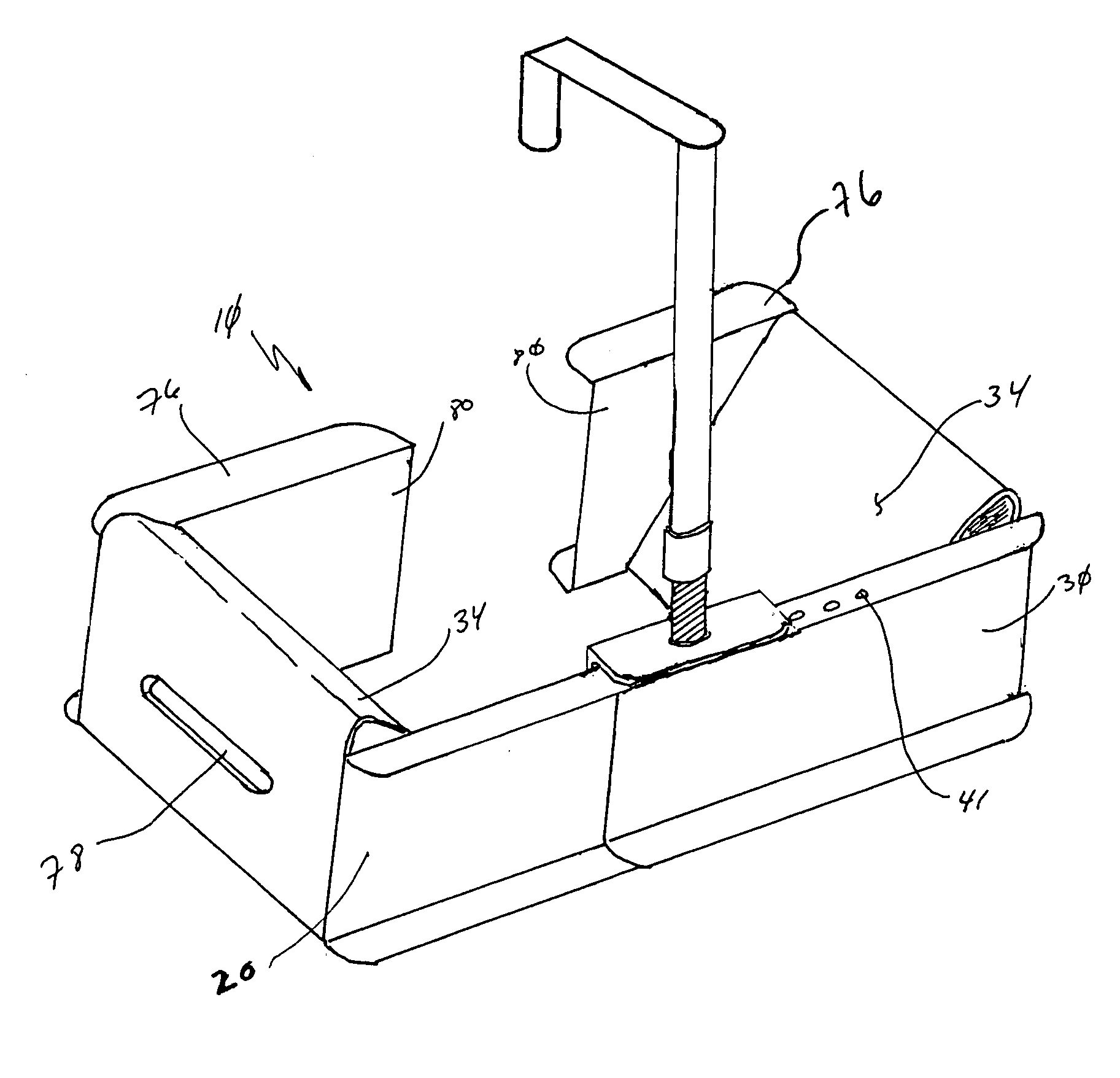
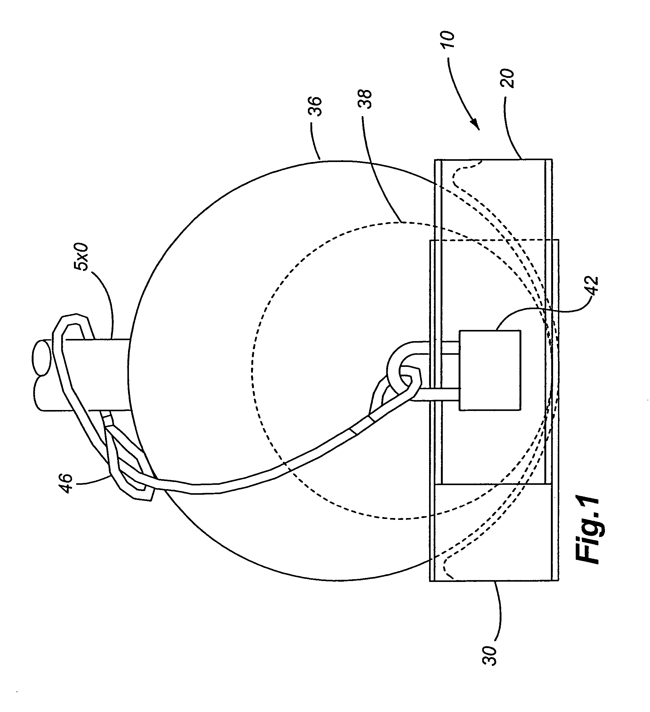
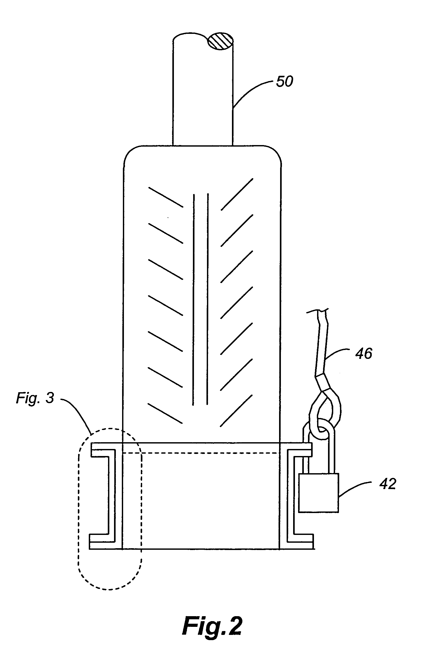
[0051]Referring now to FIGS. 1 through 21, a locking chock of the present invention is shown. More specifically, a wheel immobilization device 10 that is commonly employed on aircraft, is shown that consists of at least a forward chock 20, a rear chock 30, a lock 42, and a flexible securing mechanism, such as a chain 46. Once the aircraft is parked, a pilot or airport ground personnel, slide the forward chock 20 of the chock in front of a tire 36 on the aircraft. Next, the rear chock 30 is slid behind the tire 36 and selectively interconnected to the forward chock 20.

[0052]Referring now to FIGS. 1 through 7, one embodiment of the present invention is shown. More specifically, a locking chock 10 that includes a forward chock 20 and a rear chock 30 that selectively interconnect are shown. Preferably, the half chocks 20 and 30 each include two opposing “C” channels interconnected by a ramp 34 that is adapted for engagement with an aircraft tire 36. The ramp 34 fits the contour of the t...


PUM


Abstract

The present invention is adapted to immobilize a vehicle by utilizing a pair of selectively interconnected chocks that are placed fore and aft of a tire. The chocks are preferably used to secure aircraft and / or aircraft ground support equipment from unauthorized motion in airport parking areas.

Description

[0001]This application is a Continuation-In-Part of U.S. patent application Ser. No. 10 / 728,581, filed Dec. 4, 2003 now U.S. Pat. No. 6,896,223, which claims the benefit of U.S. Provisional Patent Application Ser. No. 60 / 431,187, filed Dec. 4, 2002, both applications incorporated by reference in their entirety herein.FIELD OF THE INVENTION[0002]The present invention relates to devices for selective interconnection to a tire of a vehicle, and more specifically to light-weight chocks used to generally prevent and deter theft and unauthorized movement of aircraft and associated ground support equipment.BACKGROUND OF THE INVENTION[0003]Wheel immobilization devices are employed in a variety of situations, most commonly being the wheel chock. Wheel chocks provide an easy and inexpensive way to ensure that a vehicle will remain at rest if a parking brake should fail. Often chocks will have a triangular or rectangular cross section, the former being the preferred shape because it approximat...

Claims


Application Information

Patent Timeline
Patent Type & Authority Patents(United States)
IPC IPC(8): B64C25/42B64F1/16
CPCB64F1/16Y10T70/585Y10T70/5841
Inventor FULCHER, ROBERT A.BEAVERS, ALLAN E.
Owner MITI MFG
Why Eureka
Try Eureka