Portable electric tool

a technology of electric tools and electric tools, applied in the field of portable electric tools, can solve the problems of difficult to move the lever from the release position, difficult to adjust the cutting depth, and large rotational force of bolts, and achieve the effect of accurate and easy adjustment of cutting depth and good operability

Active Publication Date: 2006-10-17
KOKI HLDG CO LTD
View PDF24 Cites 12 Cited by
  • Summary
  • Abstract
  • Description
  • Claims
  • Application Information

AI Technical Summary

Benefits of technology

[0009]An object of the present invention is to provide a portable electric tool having good operability which solves the problems as described above and which makes it possible to adjust the cutting depth accurately and easily.
[0011]According to one aspect of the present invention, it is possible to provide a portable electric tool having good operability which makes it possible to adjust the cutting depth accurately and easily.

Problems solved by technology

However, since a force of the cylindrical portion to restore its shape to the initial shape is applied to the bolt, it is necessary to rotate the bolt with a very large force, and operability is not good.
However, in the structure, when the lever moves from the fixed position, due to the restoration force of the cylindrical portion, the lever immediately moves to the release position, and the cylindrical housing falls off, and is detached from the cylindrical portion by its own weight.
It is difficult to move the lever from the release position to the fixed position while maintaining the positional relationship between the cylindrical housing and the cylindrical portion.

Method used


Image

  • Portable electric tool
  • Portable electric tool
  • Portable electric tool

Examples


Embodiment Construction

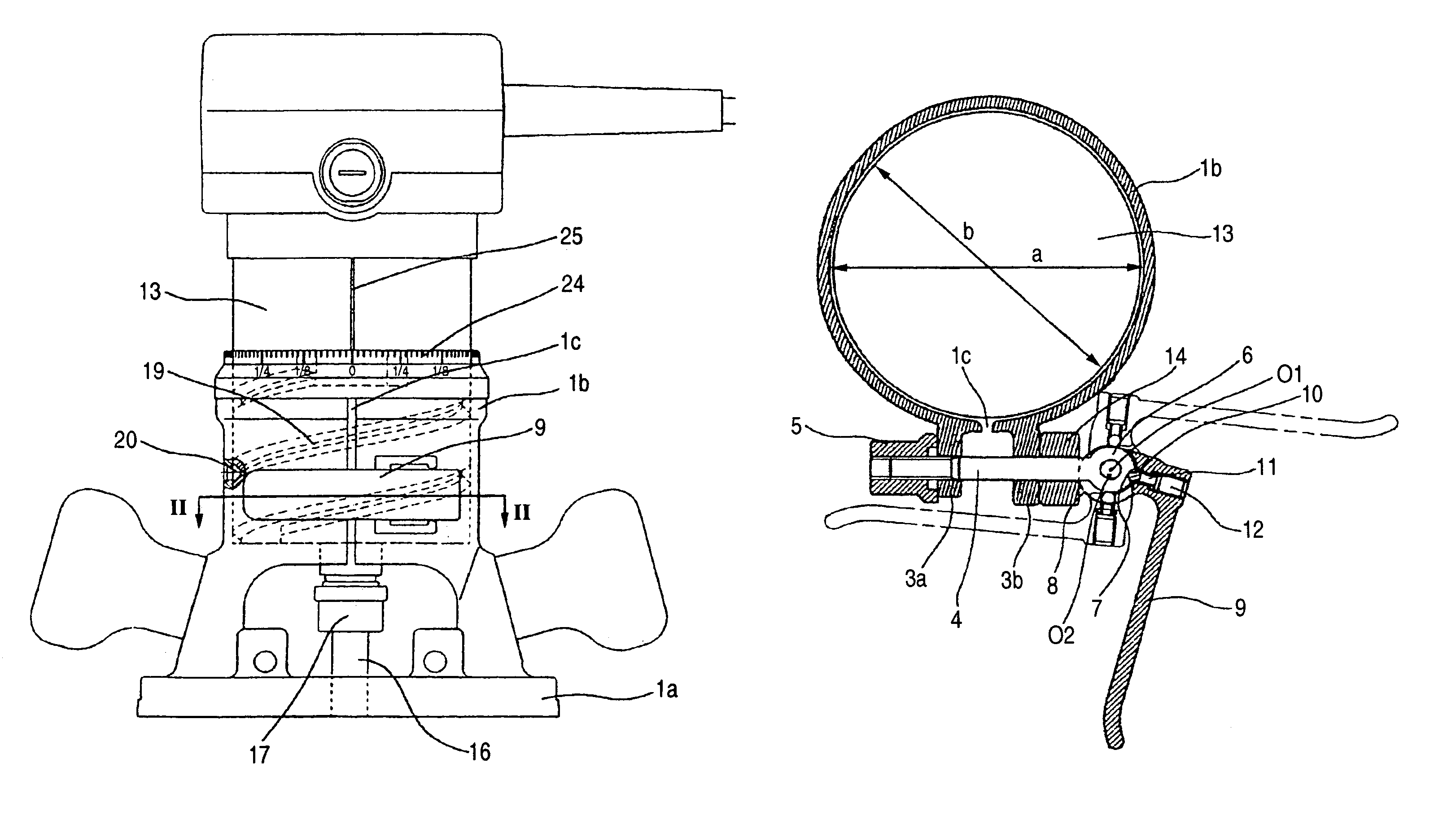
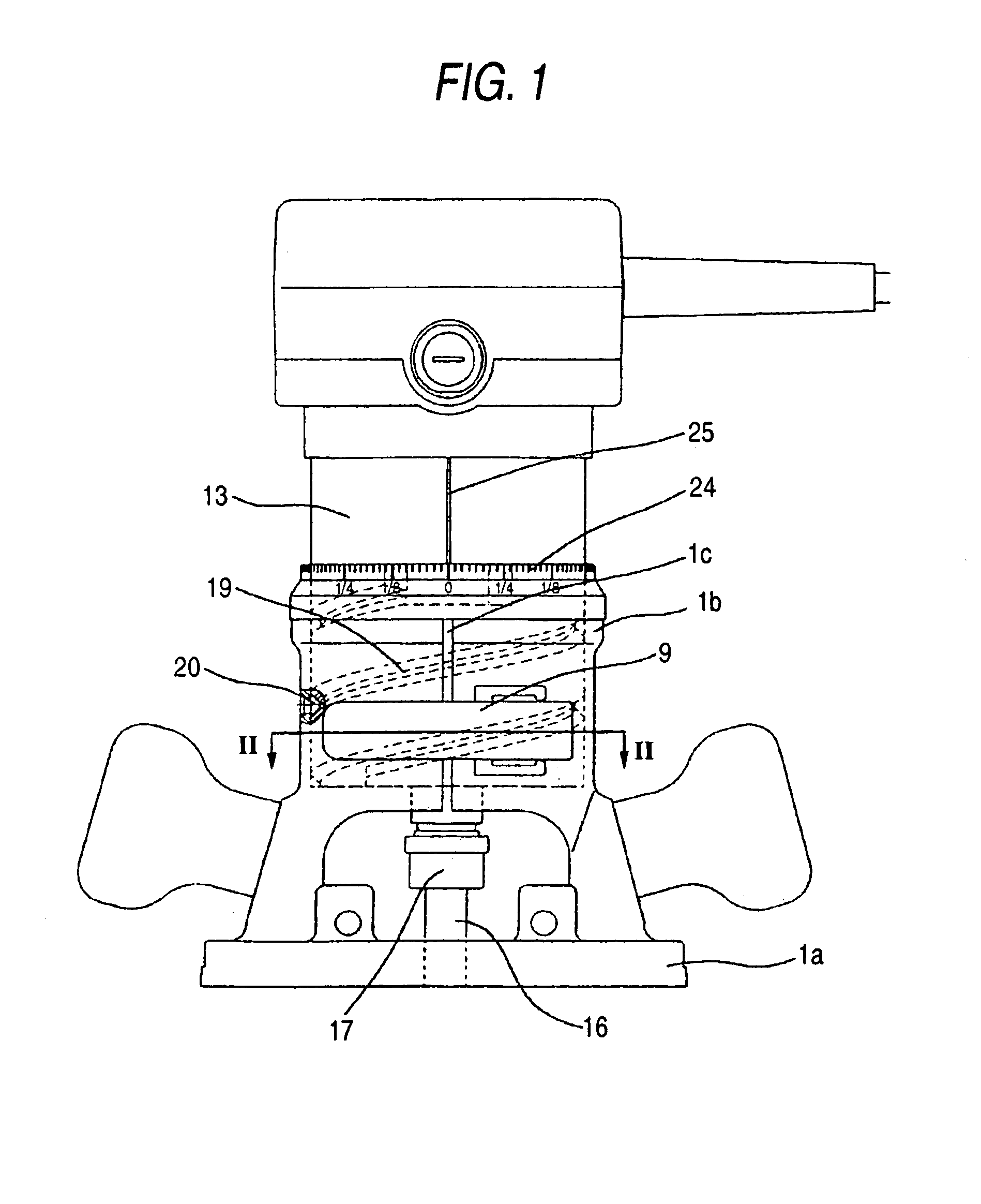
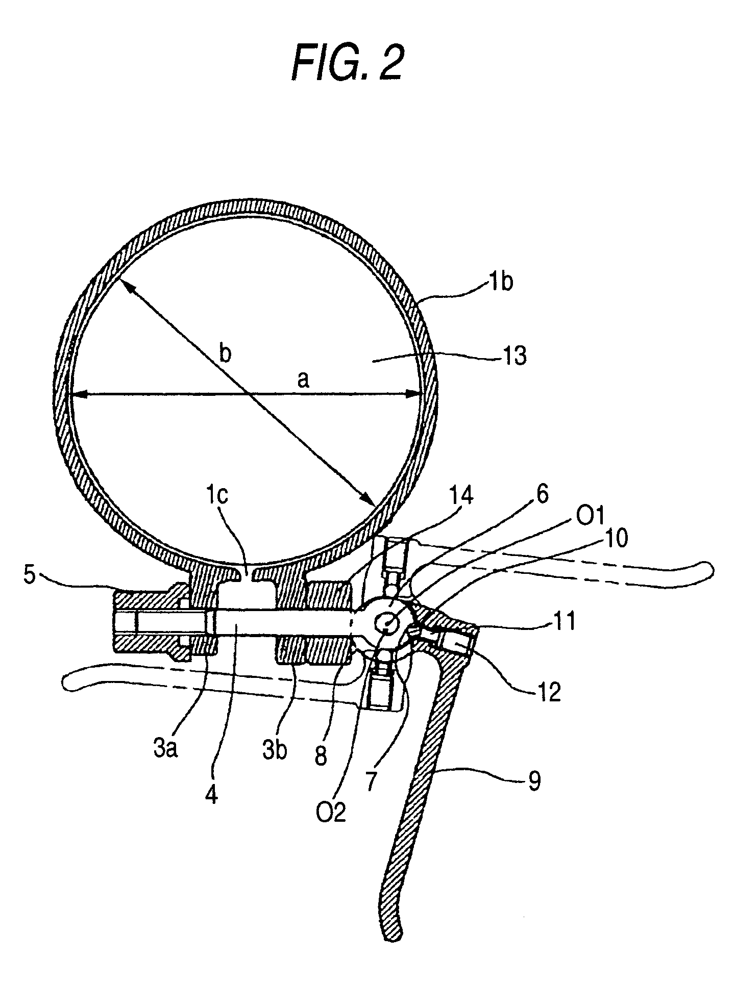
[0015]A portable router as an example of a portable electric tool according to an embodiment of the present invention will be described with reference to FIGS. 1 and 2. FIG. 1 is a front view showing the portable router according to the embodiment of the present invention. FIG. 2 is a cross sectional view taken along a line II—II in FIG. 1.

[0016]As shown in the drawings, the portable router includes a cylindrical housing 13 and abase 1. The cylindrical housing 13 accommodates a motor (not shown) and has a chuck 17 for detachably holding a tip tool 16 provided at a tip of a rotation shaft of the motor. The base 1 includes a surface plate 1a which is slidable on an upper surface of work material and the tip tool 16 which can protrude from the surface plate 1a downwardly, and the cylindrical portion 1b of which a cutout portion 1c is a substantially C-shaped cross section as shown in FIG. 2.

[0017]The dimension “a” of the inner diameter of the cylindrical portion 1b of the base 1 is lar...


PUM

PropertyMeasurementUnit
weightaaaaaaaaaa
spherical shapeaaaaaaaaaa
forceaaaaaaaaaa

Abstract

A portable electrical tool includes a tip tool; a cylindrical housing accommodating a motor including a chuck attachably and detachably holding the tip tool at tip end of a rotation shaft; a base including a surface plate which slides on an upper surface of work material, and which allows the tip tool to protrude from the surface plate downwardly, a cylindrical portion including a cutout portion, and a lever having a cam surface, and rotatable to a fixed position and a release position. When the lever is in the fixed position, a gap at the cutout portion is narrowed to stop movement of the cylindrical housing. When the lever is in the release position, the cylindrical housing is movable by weight in the cylindrical portion. The tool includes a stopper to stop a rotation of the lever between the fixed position and the release position.

Description

BACKGROUND OF THE INVENTON[0001]1. Field of the Invention[0002]The present invention relates to a portable electric tool such as a portable router or a portable trimmer having a lever for fixing a housing to a base.[0003]2. Description of the Related Art[0004]For example, a conventional portable electrical tool such as a portable router or a portable trimmer has the structure including a motor, a cylindrical housing which accommodates the base, and has a chuck provided at a tip of a rotation shaft of the motor for detachably holding a tip tool, and a base having a surface plate which slides on an upper surface of work material and allows the tip tool to protrude from the surface plate downwardly (for example, see JP-U-59-118504), and a cylindrical portion including a cutout portion to have a substantially C-shaped cross section.[0005]In the portable electric tool having this structure, a bolt provided at the cylindrical portion is rotated to deform the cylindrical portion having the...

Claims


Application Information

Patent Timeline
Patent Type & Authority Patents(United States)
IPC IPC(8): B23C1/20B27C5/10
CPCB27C5/10Y10T409/306608Y10T409/308176
Inventor ONOSE, AKIRAUCHIDA, HIROKI
Owner KOKI HLDG CO LTD
Why Eureka
Try Eureka