
Balance practicing machine

Inactive Publication Date: 2006-10-17
MATSUSHITA ELECTRIC WORKS LTD
View PDF12 Cites 37 Cited by
  • Summary
  • Abstract
  • Description
  • Claims
  • Application Information

AI Technical Summary

Benefits of technology

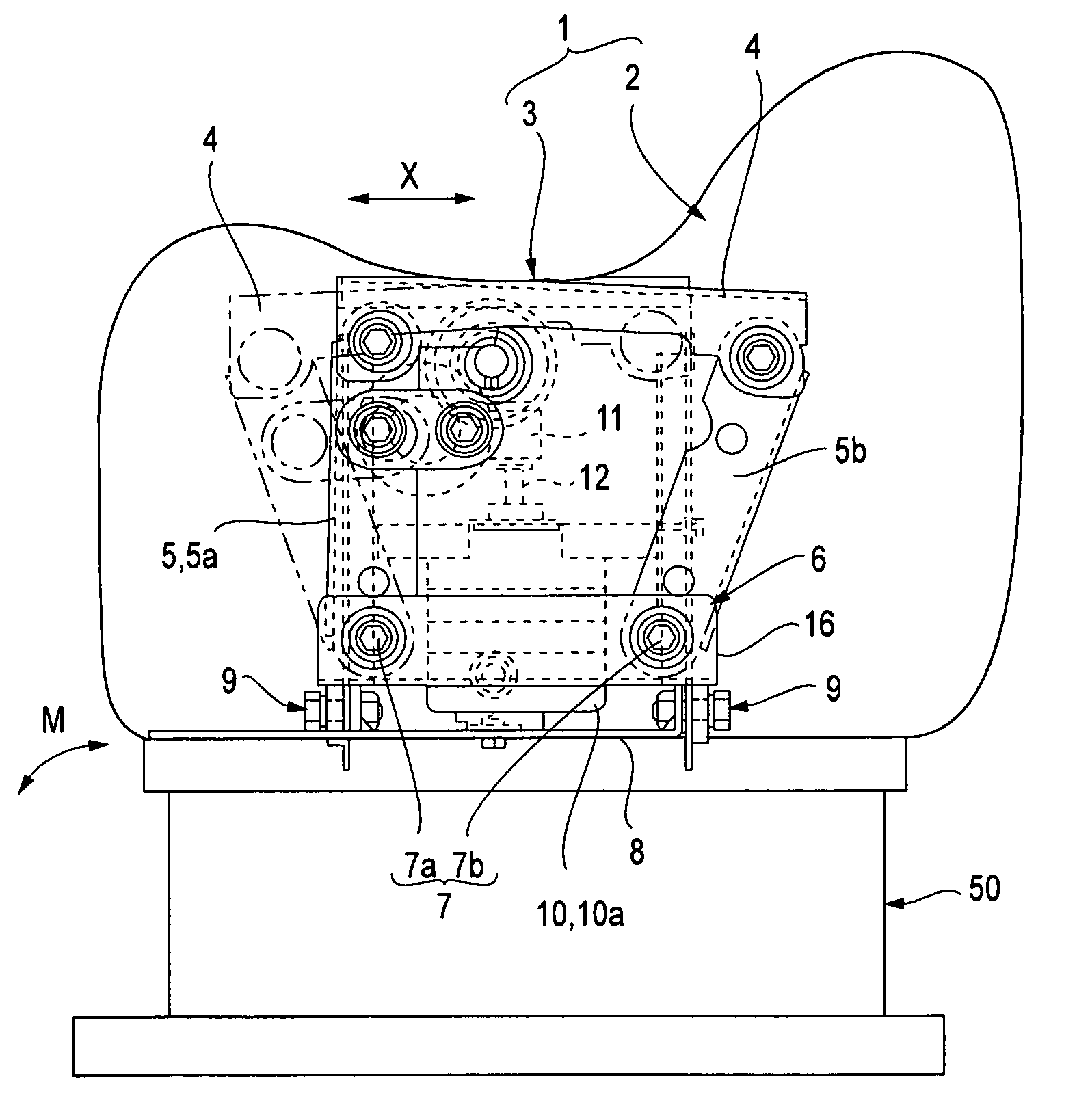
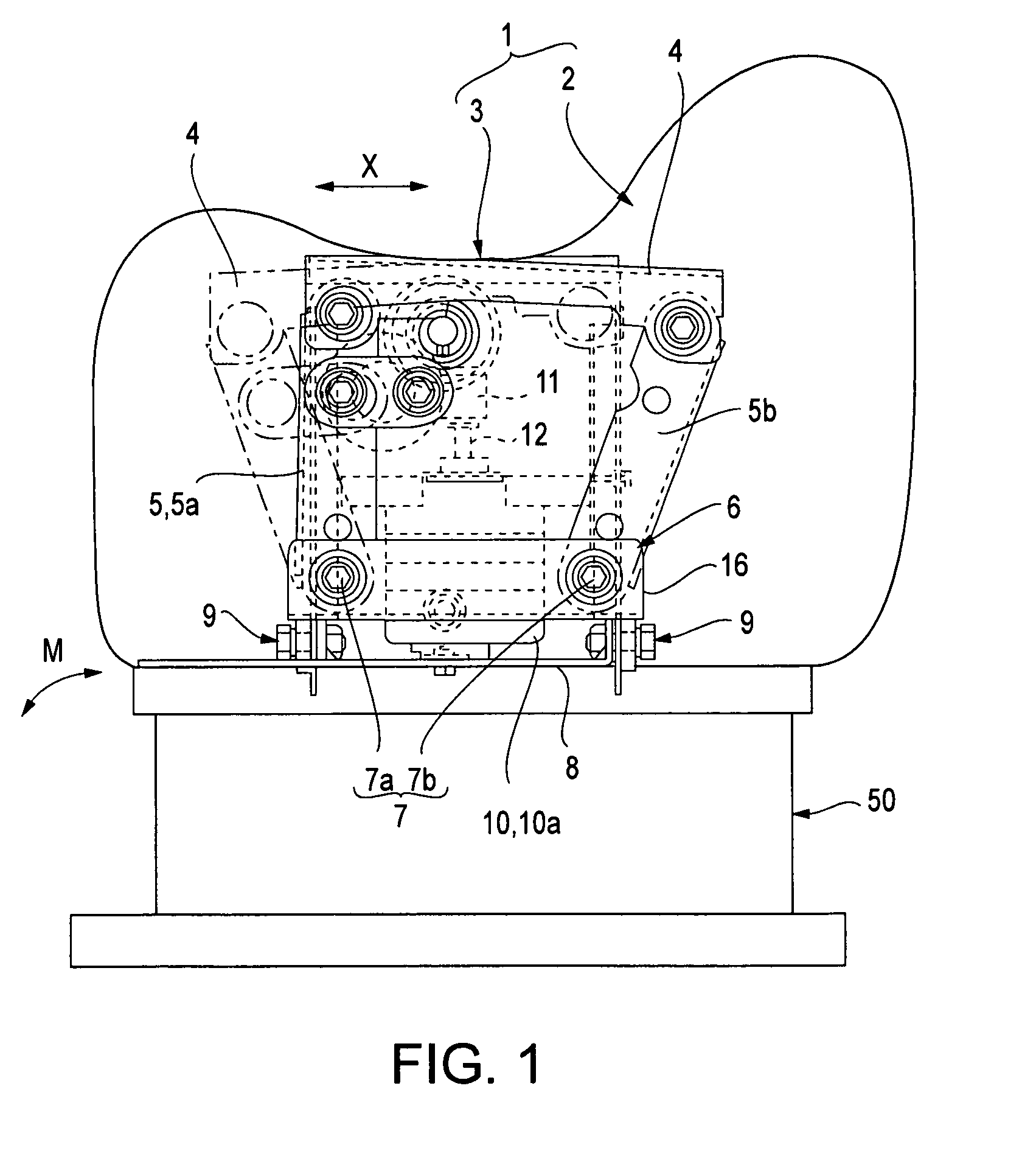
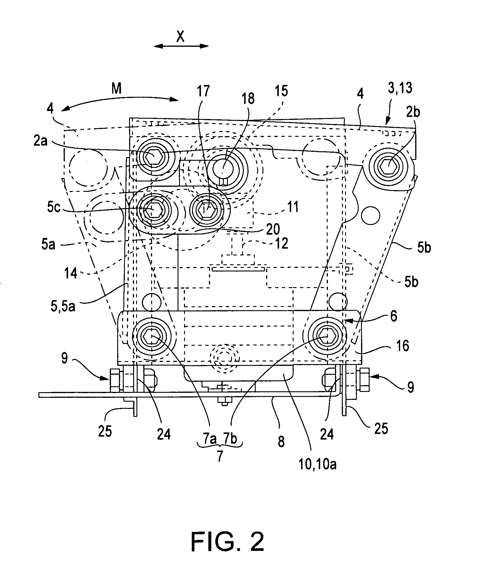
[0008]The invention, improving on the two conventional structures described above, proposes a balance practicing machine that employs a power source from which a rotating output shaft extends from one side, and that generates movements of the seat in the form of a repetitive linear motion in the fore-aft direction, a repetitive pivoting motion around a longitudinal shaft, and a repetitive pivoting motion around transverse shafts. The invention is thus able to offer the advantages of a simple control system, reduced cost, and a smaller balance practicing machine that requires less space for the drive assembly.
[0011]This construction is thus able to provide a body balancing practice and exercise function by moving the seat with fore-aft, left-right, and vertical swinging motions as three movements that include a repetitive linear motion in the fore-aft X direction, a repetitive pivoting motion around the transverse shafts, and a repetitive pivoting motion around the longitudinal shaft.
[0012]Moreover, the use of only one power source eliminates the need for multiple power sources, and because the output shaft extends from only one side of the power source, the drive assembly can be made to more compact dimensions and installed within a smaller space as compared to that required by a conventional drive assembly.
[0015]The first and second sub-transmissions offer the advantages of few required components, easy assembly, and reduced size.

Problems solved by technology

H6-65350 is equipped with six separately controlled power sources, the timing, speed, and operating range of each power source must be individually controlled, thus making for an extremely complex control system.
Moreover, the use of six power sources increases both the cost and size of the balance practicing machine.
This structure creates a problem in that a large amount of space must be provided on the horizontal plane to accommodate the bi-direction extension of output shaft 12, and that drive assembly 3 be made to relatively large dimensions.

Method used


Image

  • Balance practicing machine
  • Balance practicing machine
  • Balance practicing machine

Examples


Embodiment Construction

[0030]The particulars shown herein are by way of example and for purposes of illustrative discussion of the embodiments of the present invention only and are presented in the cause of providing what is believed to be the most useful and readily understood description of the principles and conceptual aspects of the present invention. In this regard, no attempt is made to show structural details of the present invention in more detail than is necessary for the fundamental understanding of the present invention, the description is taken with the drawings making apparent to those skilled in the art how the forms of the present invention may be embodied in practice.

[0031]The following will explain an embodiment of the present invention with reference to the attached figures. The present invention includes a balance practicing machine 1 which, as shown in FIGS. 1 through 4, is constructed in the form of a seat 2 on which a persons sits, a pedestal 50 which supports the seat 2, and a drive...


PUM


Abstract

A balance practicing machine that offers simplified control, reduced cost, and a compact drive assembly that reduces the space requirement for the machine. The machine includes an output shaft from one side of a power source to impart three movements to the seat in the form of a repetitive linear motion in the longitudinal direction, a repetitive pivoting motion around a longitudinal shaft, and a repetitive pivoting motion around transverse shafts. A seat base is connected to an active frame, through connector links, so as to provide swinging movement of the seat base around transverse shafts. The active frame is connected to a base member so as to allow the repetitive pivoting movement of the active frame around a longitudinal shaft.

Description

BACKGROUND OF THE INVENTION[0001]1. Field of Application[0002]The invention relates to a balance practicing machine that provides a swinging motion to a person sitting on the machine in order to provide balance practice and exercise.[0003]2. Description of the Related Art[0004]The related art includes a type of conventional balance practicing machine which is constructed in the shape of a horse and equipped with six power sources that generate six different movements. An example of such a conventional balance practicing machine is described in Japanese Kokou Patent No. H6-65350. These six movements consist of repetitive linear motions in the fore-aft, right-left, and vertical directions, and repetitive pivoting motions around longitudinally, transversely, and vertically oriented shafts. These motions combine to form a compound swinging movement comprised of six separately controllable movements.[0005]Another type of conventional balance practicing machine is shown in FIGS. 7 through...

Claims


Application Information

Patent Timeline
IPC IPC(8): A63B69/04A63B22/16A63B23/00A63B26/00
CPCA63B69/04A63B26/003B25C5/0214B25C5/025B25C5/11B26F1/32
Inventor HOJO, HIROYUKINAKANISHI, RYUSUKE
Owner MATSUSHITA ELECTRIC WORKS LTD
Learn More