Voltage-change control circuit and method

a control circuit and voltage technology, applied in pulse manipulation, pulse technique, instruments, etc., can solve the problems of useless power, noise problem of pump booster circuit, inability to control boost voltage without using,

Inactive Publication Date: 2006-10-17
SONY CORP
View PDF4 Cites 16 Cited by
  • Summary
  • Abstract
  • Description
  • Claims
  • Application Information

AI Technical Summary

Benefits of technology

[0026]supplying a feedback signal corresponding to the control amount to the clock buffer section thereby controlling the clock amplitude of the clock buffer section.

Problems solved by technology

In addition, the charge-pump booster circuit encounters a noise problem (pumping noise) which occurs when driving a clock buffer for a pumping clock or a pumping capacitor during a pumping operation.
Meanwhile, driving the capacitor and clock buffer section on the VDD voltage causes useless power, having an effect as a great noise source.
Furthermore, boost voltage cannot be controlled without using a potential change of VDD width=VDD step.

Method used


Image

  • Voltage-change control circuit and method
  • Voltage-change control circuit and method
  • Voltage-change control circuit and method

Examples


Embodiment Construction

[0044]Explanation will be now made of an embodiment of a voltage-change control circuit and method according to the present invention.

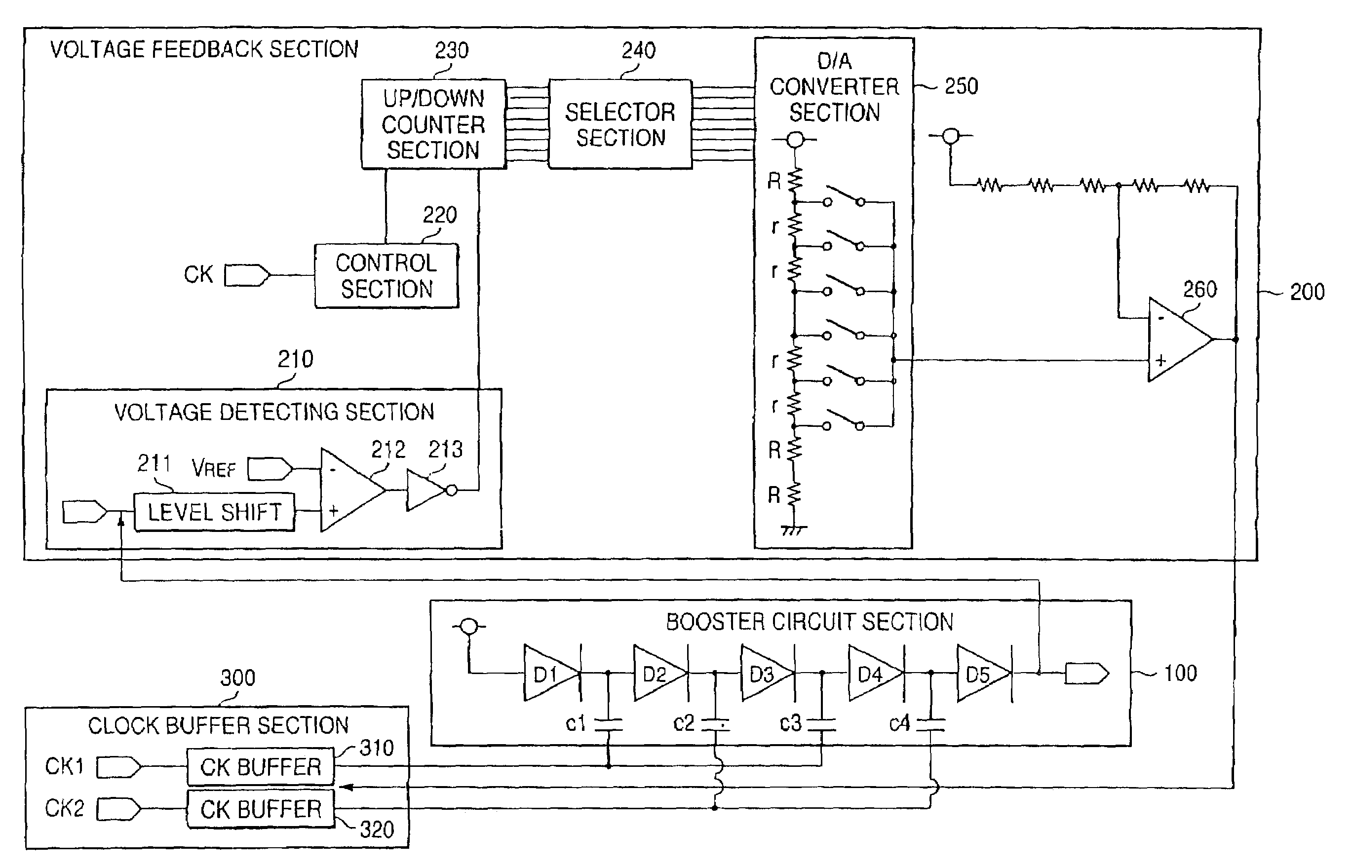
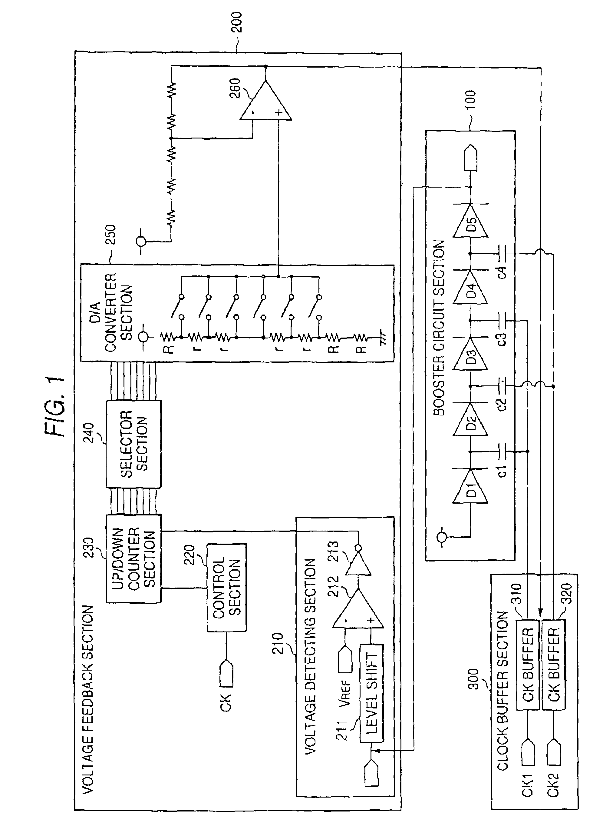
[0045]FIG. 1 is a block diagram showing a configuration of a booster circuit to which is applied a voltage-change control circuit according to an embodiment of the invention.

[0046]The booster circuit includes a booster circuit section100 for boosting an external power voltage in absolute value level, boost-voltage feedback section 200 for controlling the booster circuit section 100, and a clock buffer section 300.

[0047]The booster circuit of this embodiment is characterized in that a D / A converter is used as a control-amount determining section of the boost-voltage feedback section 200 and that boost potential is controlled by controlling the power voltage to the clock buffer section 300.

[0048]Explanation will now be made of the configuration of the booster circuit of this embodiment.

[0049]At first, the configuration of the booster circuit section 100...


PUM


Abstract

In a charge-pump booster circuit, the control clock is controlled on a small-step basis to thereby suppress the boost amplitude and the occurrence of various noises. Provided are a charge-pump booster circuit section for boosting an external power voltage in absolute value level, a boost-voltage feedback section for controlling the booster circuit section, and a clock buffer section. In the boost-voltage feedback section, an output level of the booster circuit section is detected by a voltage detecting section. This is compared with a reference level, and depending upon the comparison result, a count operation is made in an up / down counter section. Based on the count value, the control amount is shifted on a small-step basis from the D / A converter section, thereby controlling the power voltage of the clock buffer section 300 through the level shifter section.

Description

BACKGROUND OF THE INVENTION[0001]1. Technical Field of the Invention[0002]This invention relates to a voltage-change control circuit and electronic apparatus (e.g. camera) including such a voltage-change control circuit.[0003]2. Description of the Related Art[0004]Conventionally, there is known a charge-pump booster circuit used in generating a write / erase voltage to / from a flash memory, for example, or on a high-voltage generating circuit for a liquid-crystal display on a video camera, digital camera or the like.[0005]The charge-pump booster circuit has a series connection of a plurality of stages of pumping packets, each configured by one capacitor and diode, to generate a voltage higher than, e.g., a power voltage VDD of an LSI chip by boosting the voltage in each pumping packet (note that boosting in this case means a boosting in absolute value level, i.e. positively boosting for a positive polarity of power voltage, and negatively boosting for a negative polarity of power volta...

Claims


Application Information

Patent Timeline
Patent Type & Authority Patents(United States)
IPC IPC(8): G05F1/575H03K7/02H02M3/07
CPCH02M3/073G05F1/00
Inventor YASUI, YUKIHIROHIRATA, TAKAICHIHARUTA, TSUTOMU
Owner SONY CORP
Why Eureka
Try Eureka