Sea surface antenna

a surface antenna and antenna technology, applied in the field of sea surface antennas, can solve the problems of limited requirement of buoyant antennas

Inactive Publication Date: 2006-10-17
NORTEL NETWORKS LTD
View PDF5 Cites 79 Cited by
  • Summary
  • Abstract
  • Description
  • Claims
  • Application Information

AI Technical Summary

Problems solved by technology

However, there are applications in which a buoyant antenna is required which is limited to smaller dimensions imposed by physical constraints in its operating environment.

Method used


Image

  • Sea surface antenna
  • Sea surface antenna

Examples


Embodiment Construction

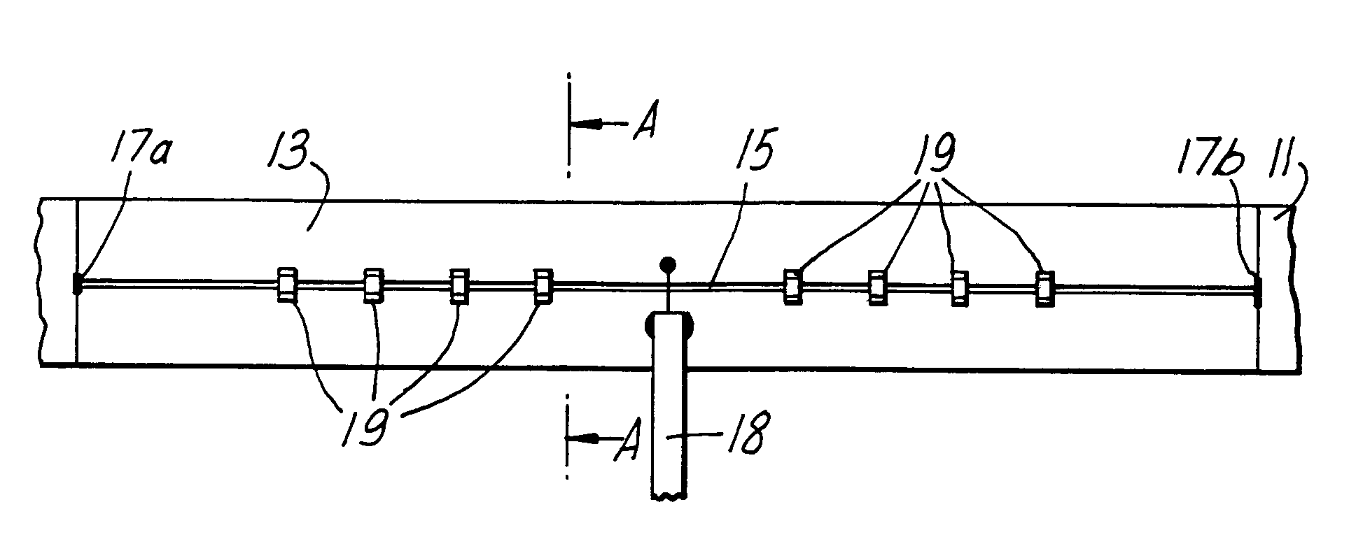
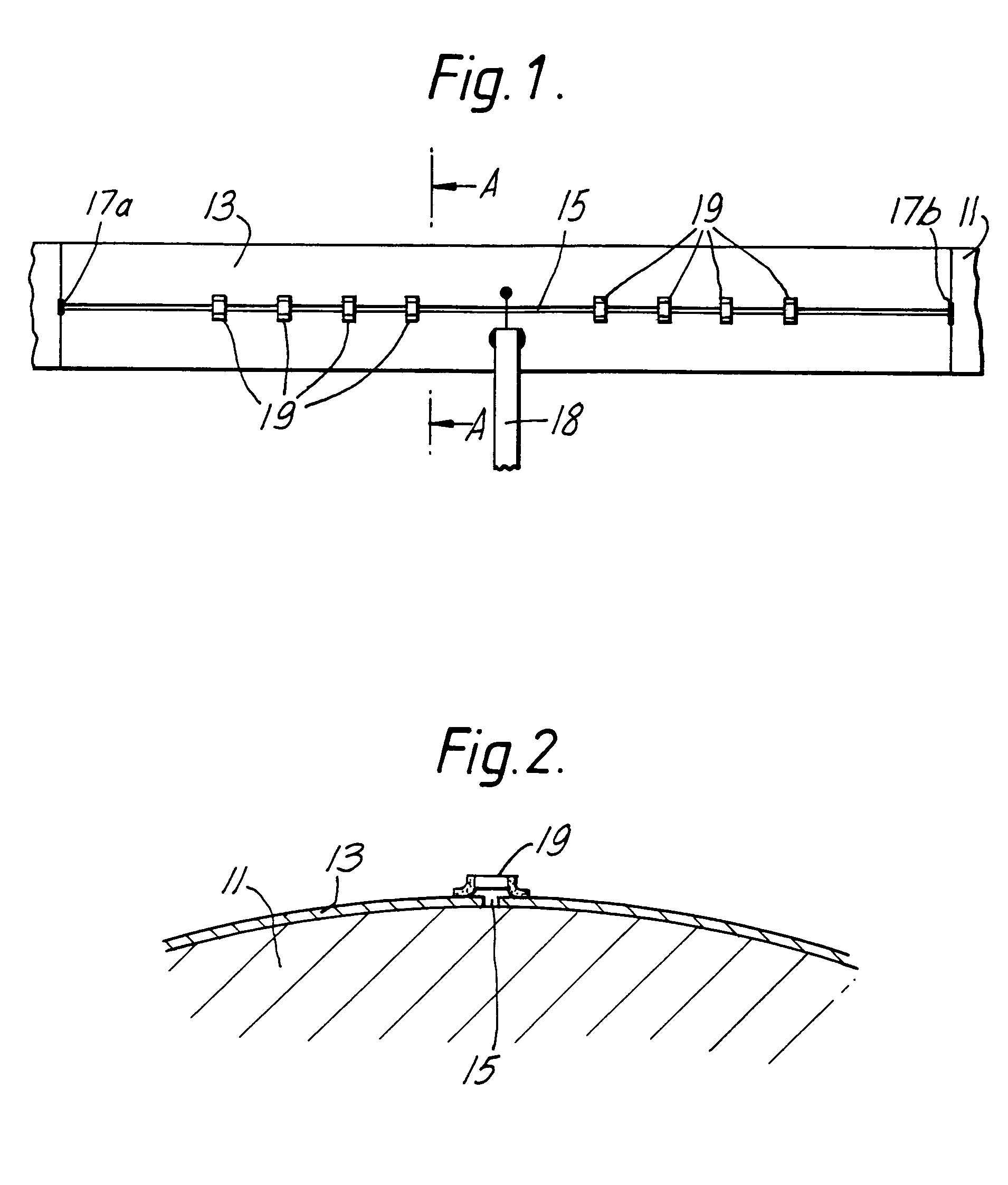
[0007]The antenna shown in the drawings comprises a rigid cylindrical dielectric former 11 having a cladding of copper 13. A narrow longitudinal slot 15 is machined in the copper cladding. The ends 17a, 17b of the slot 15 are shorted and across the midpoint of the slot are soldered the two conductors of a coaxial cable 18 that feeds the antenna. A number of discrete capacitors 19 are mounted across the slot along its length in two equal groups in a configuration that is symmetrical about the feed point.

[0008]The exact symmetry described is not essential but is a convenient design feature.

[0009]It is important to note that the capacitors do not simply tune and match the antenna input impedance, but that they also modify the voltage distribution along the radiating slot. The feature is used to combat the evanescent nature of the antenna and to produce an effective length substantially greater than if the capacitors were not present, and hence to improve the antenna efficiency.

[0010]Wh...


PUM


Abstract

A sea surface antenna comprises a cylindrical tube of metallic material 13 on a dielectric former. The tube has a longitudinal slot shorted at each end and coupled at its midpoint to a coaxial feed. The slot is bridged by two groups of capacitances each group being distributed along a respective half of the slot. The length of the antenna is less than 0.25 λ and the diameter of the antenna is less than 0.02 λ, where λ is the free space wavelength at the operating frequency. The antenna is dimensioned so as to operate in an evanescent mode at a resonant frequency less than the cut-off frequency.

Description

[0001]This invention relates to a sea surface antenna which can be towed behind a marine craft for radio communication purposes.BACKGROUND OF THE INVENTION[0002]A so-called buoyant antenna is disclosed in the paper “A Slender Resonator—Slot Antenna” by J. C. Lee, IEE International Conference on Antennas and Propagation, Conf. Publ. No. 195, pp 442–446, 1981. Essentially the antenna disclosed comprises a slot formed by the edge opening in a roll-resonator of copper clad plastic dielectric, approximately ½ free-space wavelength long. The slot is short circuited at the two ends, and the antenna is fed by a coaxial line the inner and outer conductors of which are soldered to respective sides of the slot. A modified antenna is disclosed in “UHF Buoyant Antenna” by M. S. Smith et al, IEE ICAP 87, pp 1.273–1.276, 1987. The modified antenna augments the “per unit length” capacitance by discrete capacitors connected across the slot, the length of the antenna being approximately equal to λ / 2,...

Claims


Application Information

Patent Timeline
Patent Type & Authority Patents(United States)
IPC IPC(8): H01Q1/34H01Q13/10H01Q1/04H01Q13/12
CPCH01Q1/04H01Q1/34H01Q13/12
Inventor SMITH, MARTIN STEVENSADAMS, DAVID NEIL
Owner NORTEL NETWORKS LTD
Why Eureka
Try Eureka