Bearer integration method and apparatus for the bearer integration method

a technology of bearer integration and integration method, which is applied in the direction of synchronisation transmitter, multiplex communication, synchronisation arrangement, etc., can solve the problems of low possibility that a wireless channel of the same frame offset is unoccupied, bearer integration is not available for bearer service, and bearer integration is not possible to perform bearer integration between wireless channels. achieve the effect of increasing the number of wireless channels which can be used

Inactive Publication Date: 2006-10-17
FUJITSU LTD
View PDF3 Cites 19 Cited by
  • Summary
  • Abstract
  • Description
  • Claims
  • Application Information

AI Technical Summary

Benefits of technology

[0031]According to the above-mentioned invention, possibility for being able to perform bearer integration increases in any communication system in which each wireless channel has a different frame offset. Thus, the number of wireless channels which can be used increases substantially.

Problems solved by technology

Therefore, in such a communication system, there is a very low possibility that a wireless channel of the same frame offset is unoccupied when performing bearer integration.
Thus, it is impossible to perform bearer integration between wireless channels which have different frame offsets without instantaneous interruption.
According to the above-mentioned conventional method, bearer integration is not available for the bearer service which does not permit the instantaneous interruption.
In addition, the number of the wireless channels can not be increased due to such a restriction.

Method used


Image

  • Bearer integration method and apparatus for the bearer integration method
  • Bearer integration method and apparatus for the bearer integration method
  • Bearer integration method and apparatus for the bearer integration method

Examples


first embodiment

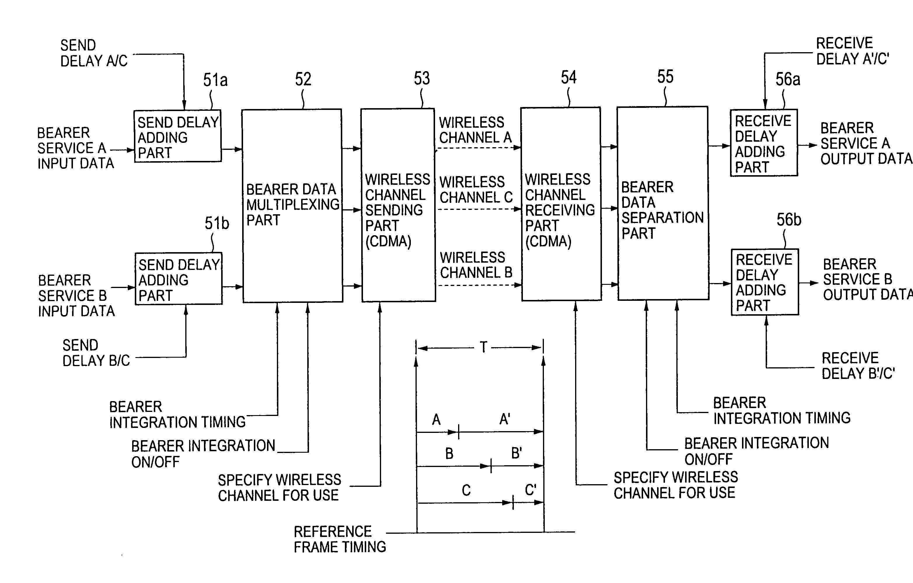
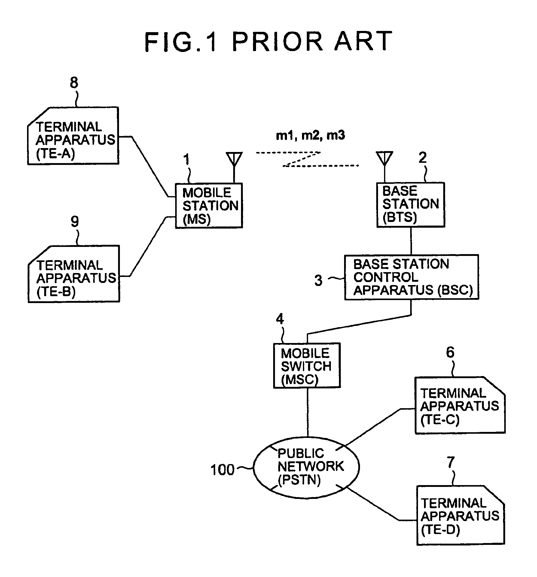
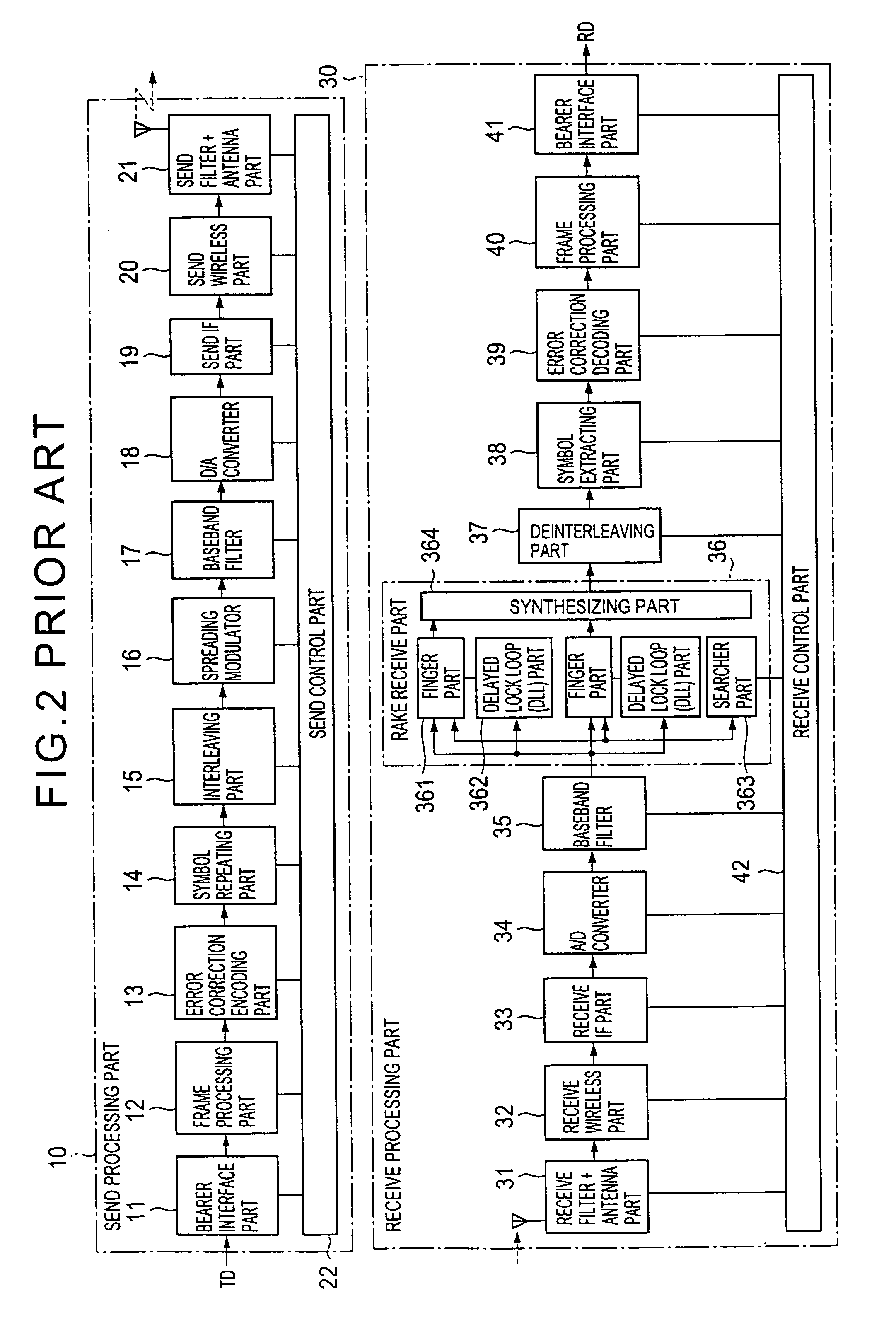
[0085]FIG. 9 shows a block diagram of a part of a mobile communication system according to the present invention. According to the configuration shown in FIG. 9, control of delay allocation of one frame period T in total is shared between the sending side and the receiving side. In addition, this figure shows a case in which bearer integration is possible from bearer services having a small frame offset to a bearer service having the same or a larger frame offset. The whole configuration of the mobile communication system may be the same as that shown in FIG. 1. In FIG. 9, the part (route) relating to bearer integration control is arranged such that it is easy to understand. The techniques described with reference to FIGS. 2 and 4 can be used for detailed configurations for each part.

[0086]In FIG. 9, the numeral 3 indicates a base station control apparatus according to the first embodiment of the present invention, 71 indicates a bearer service interface part, 72 indicates a send de...

second embodiment

[0103]FIG. 11 shows a block diagram of a part of a mobile communication system according to the present invention. According to the configuration shown in FIG. 11, control of delay allocation of 2 frame period 2T in total is shared between the sending side and the receiving side. In addition, according to the mobile communication system shown in FIG. 11, bearer services of any frame offset can be integrated into a bearer service of any frame offset. In FIG. 11, 72A indicates a send delay adding part which can delay bearer data which is before being multiplexed by within 0≦t≦2T, and 64A indicates a receive delay adding part which can delay bearer data which is separated by within 0 t 2T. Other parts may be the same as those described with reference to FIG. 9.

[0104]FIG. 12 shows a timing chart (1) of bearer integration control according to the second embodiment. The timing chart shows an example in which bearer services A, B which are in communication having frame offsets Da, Db (>Da)...

third embodiment

[0111]FIG. 15 shows a block diagram of a part of a mobile communication system according to the present invention. According to the configuration shown in FIG. 15, control of delay allocation of 2 frame period 2T in total is shared between the sending side and the receiving side, and delay of wireless transmission data which occurs when bearer integration is performed can be improved.

[0112]In FIG. 15, 72B indicates a send delay adding part which can output two kinds of delay data simultaneously for each bearer service in accordance with set send delay, 73B indicates a bearer data multiplexing part which can set timing of bearer multiplexing for each bearer service such that each bearer data input from the send delay adding part 72B becomes two wireless channels for the terminal station 1 simultaneously, 63B indicates a bearer separation part which outputs bearer data multiplexed irregularly as two kinds of bearer data for each bearer service in accordance with the receive control pa...


PUM


Abstract

A bearer integration method for integrating a plurality of bearer services into a wireless channel by performing time-division multiplexing/demultiplexing is provided, in which bearer service data is input in synchronization with reference frame timing of a period T in a sending side, the bearer service data is delayed by one frame period by allocating delays A (0≦A≦T) and A′ (=T−A) between the sending side and a receiving side, the bearer service data is output in the receiving side, and the bearer service data is integrated into a wireless channel with another bearer service data in which delays B (A≦B≦T) and B′ (=T−B) are allocated between the sending side and the receiving side.

Description

BACKGROUND OF THE INVENTION[0001]1. Field of the Invention[0002]The present invention generally relates to a bearer integration method and an apparatus for the method. More particularly, the present invention relates to a bearer integration method and apparatus for integrating a plurality of bearer services to a wireless channel by time-division multiplexing / demultiplexing with baseband processing.[0003]In a wireless communication in a CDMA system, since a plurality of terminal (mobile) stations use the same radio frequency, the CDMA system is controlled such that each terminal communicates with smaller power by using several technologies such as soft handoff. In addition, interference is suppressed so as to increase the number of available wireless channels. Further, in the CDMA system, a plurality of bearer services can be used via a terminal station. In this case, if a wireless channel is used for each of the bearer services, wireless channels and the power can not be used effect...

Claims


Application Information

Patent Timeline
Patent Type & Authority Patents(United States)
IPC IPC(8): H04J3/06H04J3/04H04B7/26H04J3/00H04J13/00H04L7/00H04W56/00H04W72/04
CPCH04J3/04H04L7/0091H04W56/00H04W88/04
Inventor UENO, TOMOYUKI
Owner FUJITSU LTD
Why Eureka
Try Eureka