
Clock, data and time recovery using bit-resolved timing registers

Inactive Publication Date: 2006-10-17
RPX CORP +1
View PDF14 Cites 3 Cited by
  • Summary
  • Abstract
  • Description
  • Claims
  • Application Information

AI Technical Summary

Benefits of technology

[0008]We have discovered that, in addition to using the recovered transmitter clock to capture and align the words of an incoming data stream, it is advantageous to accurately measure and capture the phase difference between an incoming data word from an individual transmitter and the local receiver clock. The difference is measured in the word alignment circuitry by determining the offset of the data word as positioned in at least a first register of the word circuitry. This offset is measured by determining the difference between a) the location of a first available position within a first data register and b) that position of a selected bit of the data word within that data register or within an adjacent data register. Since each bit position within the register is filled sequentially at a known fraction of a clock frequency, offset within the register is equal to the phase difference between the recovered transmitter clock associated with a data word and the receiver clock.
[0010]Once measured, the aforementioned phase difference and time delay are used to time the transmission of data from individual transmitters in the network with a maximum efficiency while, at the same time, preventing conflicts between successive data words transmitted by different transmitters.

Problems solved by technology

Further, the data may be variably delayed through the transmission medium as well as through the receiver circuitry.
For instance, the use of elastic buffers in burst-mode clock and data recovery circuits, such as first-in-first-out buffers (FIFOs), introduces timing delays that prevent the efficient control and minimization of inter-burst time gaps.
While such methods sufficiently recover clock and data for continuous or pseudo-bursty data, they are ineffective at CDR in burst mode systems.
However, while the prior methods such as those disclosed in the '290 patent and the '872 patent provide a method of accurately recovering the transmitted clock and data, the clock information was only used to assist the receiver in capturing and correlating the incoming data for further transmission within the network.

Method used


Image

  • Clock, data and time recovery using bit-resolved timing registers
  • Clock, data and time recovery using bit-resolved timing registers
  • Clock, data and time recovery using bit-resolved timing registers

Examples


Embodiment Construction

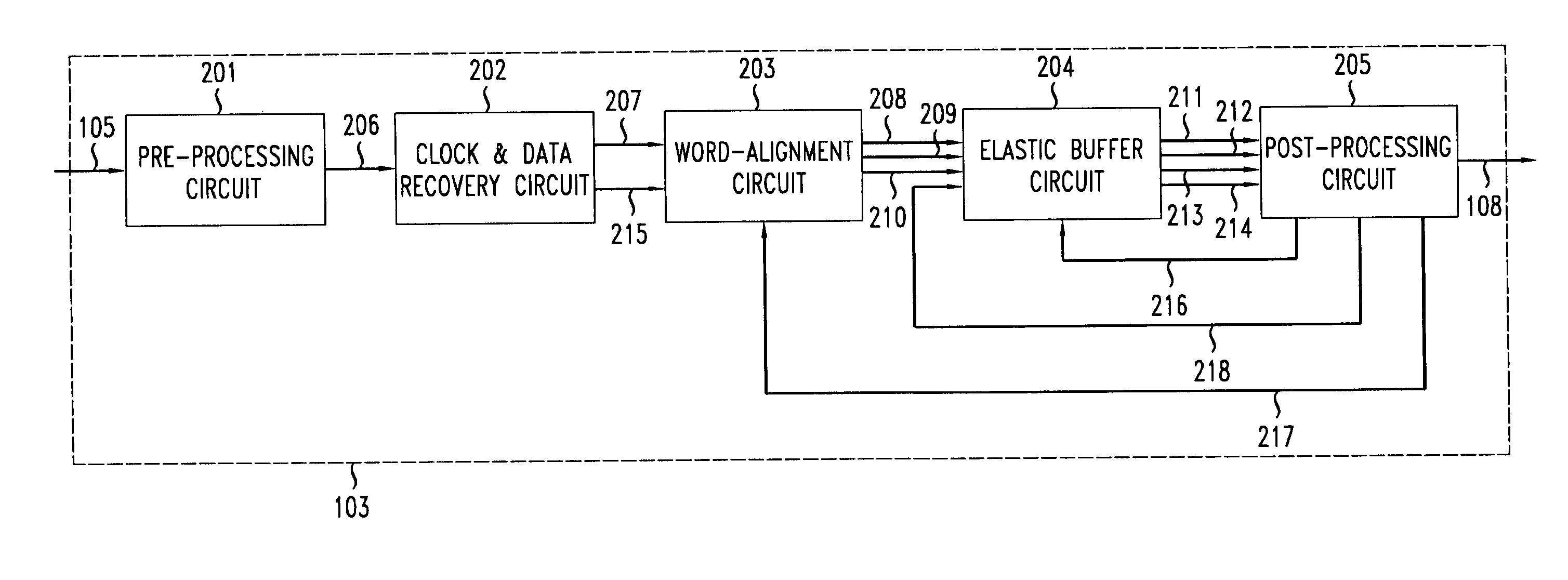
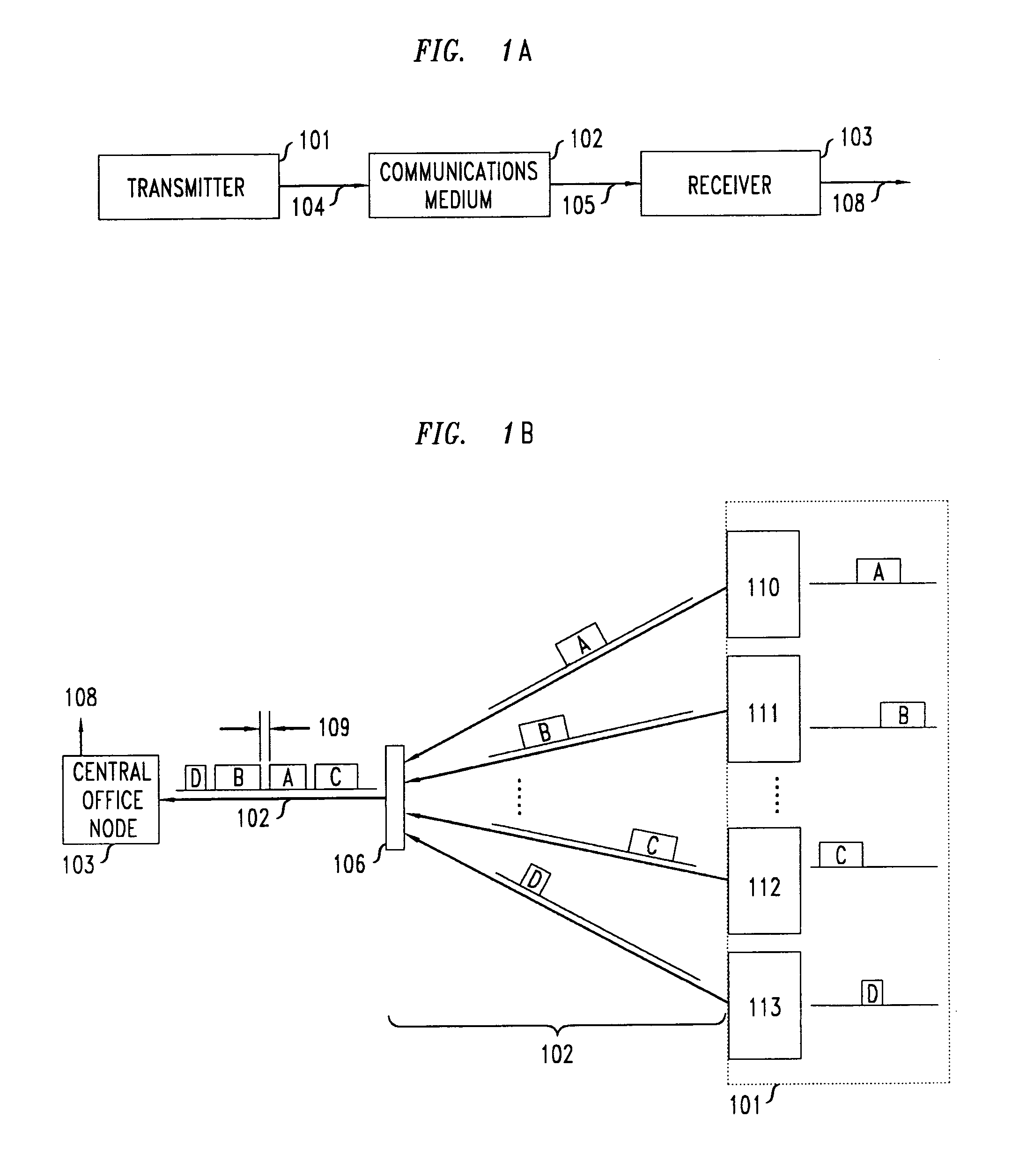
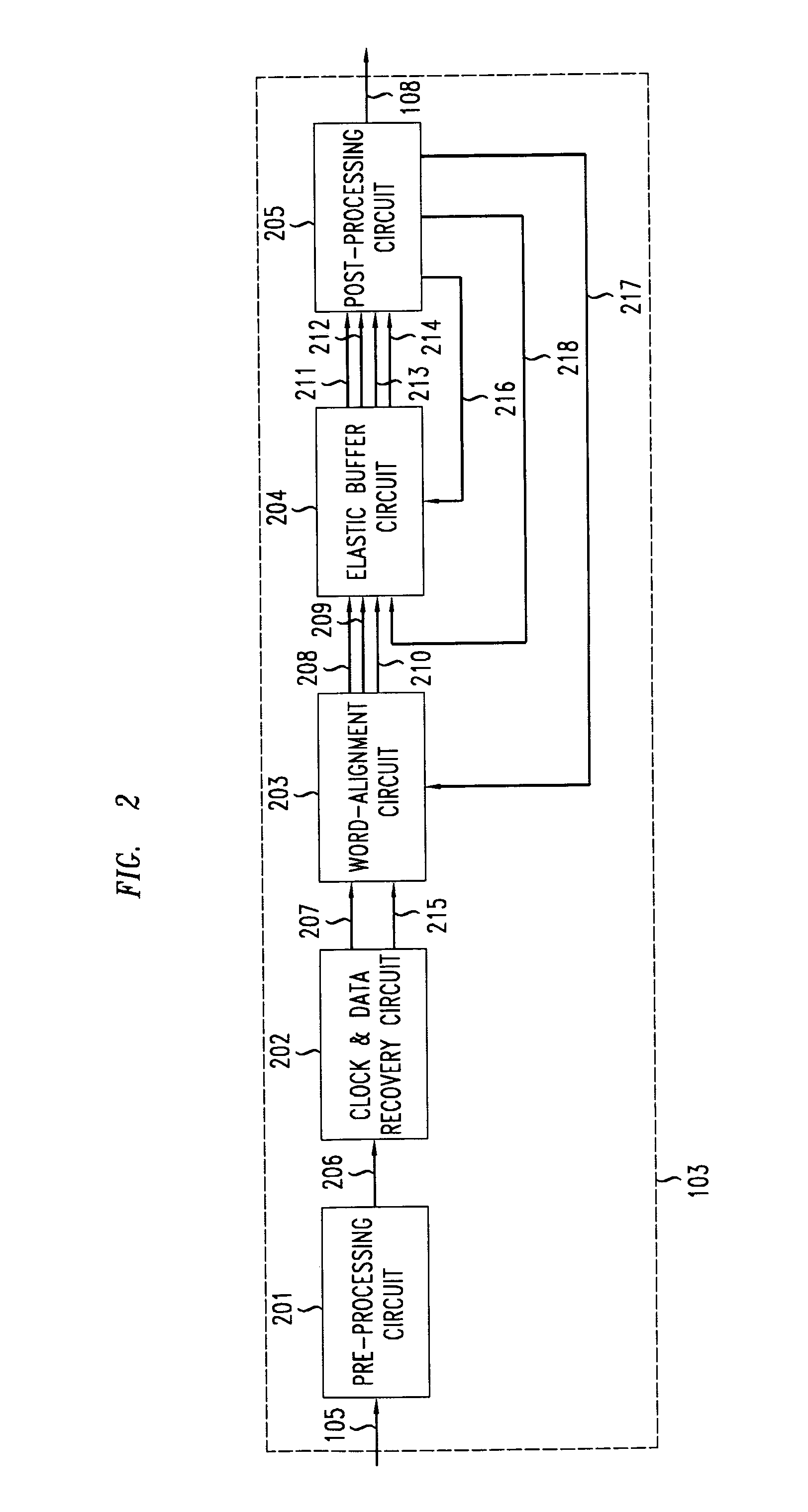
[0018]FIG. 1A shows an illustrative communications network having a transmitter 101, a communication medium 102, and a receiver 103, connected as shown in the FIG. 1. Data 104 are outputted by the transmitter 101 into the communication medium 102 and is carried by medium 102 to receiver 103 as input data stream 105. The receiver 103 decodes input data stream 105 to produce output 108, which comprises an output data word stream supplemented with timing information.

[0019]FIG. 1B shows more specific illustrative communications network, namely a time-division multiple access (TDMA) passive optical communication network (PON) having multiple user transmitter nodes 110–113, within a group of transmitters 101, transmitting and receiving data from a central office node 103. While a TDMA PON is one representative example, one skilled in the art will recognize that the principles of the present invention may be applied to any network with one or more transmitter nodes that requires accurate t...


PUM


Abstract

A clock recovery method is disclosed wherein the FIFO delay of data words and the phase difference between a data word and a receiver clock are used to time data transmissions from a transmitter. The phase difference between the data word and the receiver clock is determined by the offset of a word relative to a desired position in a storage buffer. The FIFO delay is determined either by measuring the difference between a read pointer and a write pointer in the FIFO or, alternatively, by calculating the difference between a timestamp of the time a data word entered the FIFO and the current time as the data word is read from the FIFO.

Description

FIELD OF THE INVENTION[0001]The present invention relates to digital transmission networks and, more specifically, to enhancing the efficiency of data transmission in such networks.BACKGROUND OF THE INVENTION[0002]There are numerous manners in which to transfer data from a transmitter to a receiver. In a typical system for transferring data, a transmitter has clock circuitry that controls the speed at which data are transferred via a communications medium. A receiver in such a system also typically has clock circuitry that controls the speed at which the data that are received from the communications medium is processed.[0003]Ideally, the receiver's clock and the transmitter's clock will operate at exactly the same frequency and will be appropriately aligned in phase. However, the clock used by the transmitter is typically different in phase and slightly different in frequency as compared to that of the receiver. Further, the data may be variably delayed through the transmission med...

Claims


Application Information

Patent Timeline
IPC IPC(8): H04L7/00H04J3/06H04J3/16H04L7/04
CPCH04J3/0682H04J3/1694H04L7/042
Inventor BOLES, GLENN MDUNLOP, ALFRED EARLHADZIC, ILIJAMATTHEWS, MANYALIBO JOSEPHSUVAKOVIC, DUSANVAN VEEN, DOUTJE T.
Owner RPX CORP
Features
  • Generate Ideas
  • Intellectual Property
  • Life Sciences
  • Materials
  • Tech Scout
  • Unparalleled Data Quality
  • Higher Quality Content
  • 60% Fewer Hallucinations
Learn More