Liquid-discharging head, liquid-discharging device, and method of producing the liquid-discharging head

a liquid-discharging head and liquid-discharging technology, applied in the field of liquid-discharging heads, liquid-discharging apparatuses, methods for manufacturing liquid-discharging heads, can solve the problems of small changes in print quality, semiconductor performance, cracking and chipping

Inactive Publication Date: 2006-10-24
SONY CORP
View PDF6 Cites 0 Cited by
  • Summary
  • Abstract
  • Description
  • Claims
  • Application Information

AI Technical Summary

Benefits of technology

[0014]In view of the above-mentioned problems, the present invention provides a liquid-ejecting head, a liquid-ejecting apparatus, and a method for manufacturing the liquid-ejecting head in which various types of damage due to cracking and chipping can be prevented even during high-speed dicing.
[0016]In accordance with the structure of the present invention, the present invention can be applied to liquid-ejecting heads ejecting droplets by driving the energy transducers, for example, liquid-ejecting heads which eject ink droplets, dye droplets, droplets for forming protective layers, or the like; liquid-ejecting heads for microdispensers, measuring units, or testing units which eject droplets of reagents or the like; and liquid-ejecting heads for pattern-drawing units which eject droplets of agents that protect target components during etching. In accordance with the structure of the present invention, since at least one groove is formed, parallel to at least the side face along which the energy transducers are provided, by removing insulating films, the grooves can be formed simultaneously in a step of patterning the insulating films. Thus, the grooves are efficiently formed without increasing the number of processing steps. Such grooves prevent the propagation of cracking and chipping to the chips, reduce the size of chipping fragments, prevent penetration of liquid into the chips through the cracked or chipped portions, reduce the change in fluid resistance in the ink passage, and reduce the damage due to chipping fragments. As mentioned above, various types of damage due to cracking and chipping can be prevented by the grooves even during high-speed dicing.
[0018]In accordance with the structure of the present invention, the present invention can provide a liquid-ejecting apparatus in which various types of damage due to cracking and chipping can be prevented even during high-speed dicing.
[0020]In accordance with the structure of the present invention, the present invention can provide a method for manufacturing the liquid-ejecting heads in which various types of damage due to cracking and chipping can be prevented even during high-speed dicing.

Problems solved by technology

The collision of the blade with the silicon wafer at high speed is a possible cause for cracking and chipping.
When cracking or chipping occurs in the chip, the ink can penetrate into the chip and may cause instability of semiconductor performance.
When ink is introduced to the ink chambers from a side face of the chip, the fluid resistance in the ink passage connected to the ink chambers may change due to cracking or chipping, resulting in slight changes in print quality.
Furthermore, when the chipping fragments remain on the chip surface, these fragments can damage the chip surface during forming of the ink chambers.
In the event that the damage from the chipping fragments reaches inside the chip, ink will penetrate into the chip, and a wiring pattern or the like may be damaged in the case of severe damage.
Thus, the known dicing step for cutting chips at low speed to avoid cracking and chipping disadvantageously takes time.
Besides, since it is not possible to avoid the chipping fragments, damage to the chip surfaces from the fragments is inevitable.

Method used


Image

  • Liquid-discharging head, liquid-discharging device, and method of producing the liquid-discharging head
  • Liquid-discharging head, liquid-discharging device, and method of producing the liquid-discharging head
  • Liquid-discharging head, liquid-discharging device, and method of producing the liquid-discharging head

Examples


first embodiment

1.2 Operation of First Embodiment

[0046]In the structure described above, the printing head 11 according to this embodiment (shown in FIG. 5) is completed as follows: The transistors 22 and 23, the heating devices 17 and the like are sequentially formed on the silicon wafer 40; the wafer is cut with a dicing machine into the individual head chips 12 (shown in FIG. 6); the dry film 13 is press-bonded to the head chip 12 and processed; and the orifice plate 14 is provided to form the ink chambers 15, the ink passage 16, and the like.

[0047]In the printing head 11, ink is introduced to the ink chambers 15 formed as mentioned above through the ink passage 16 formed at the side of the head chip 12. The droplets from ink contained in the ink chambers 15 are ejected from the nozzles 19 by driving the heating devices 17 with the transistors 22 and 23, and land on a target, for example, paper.

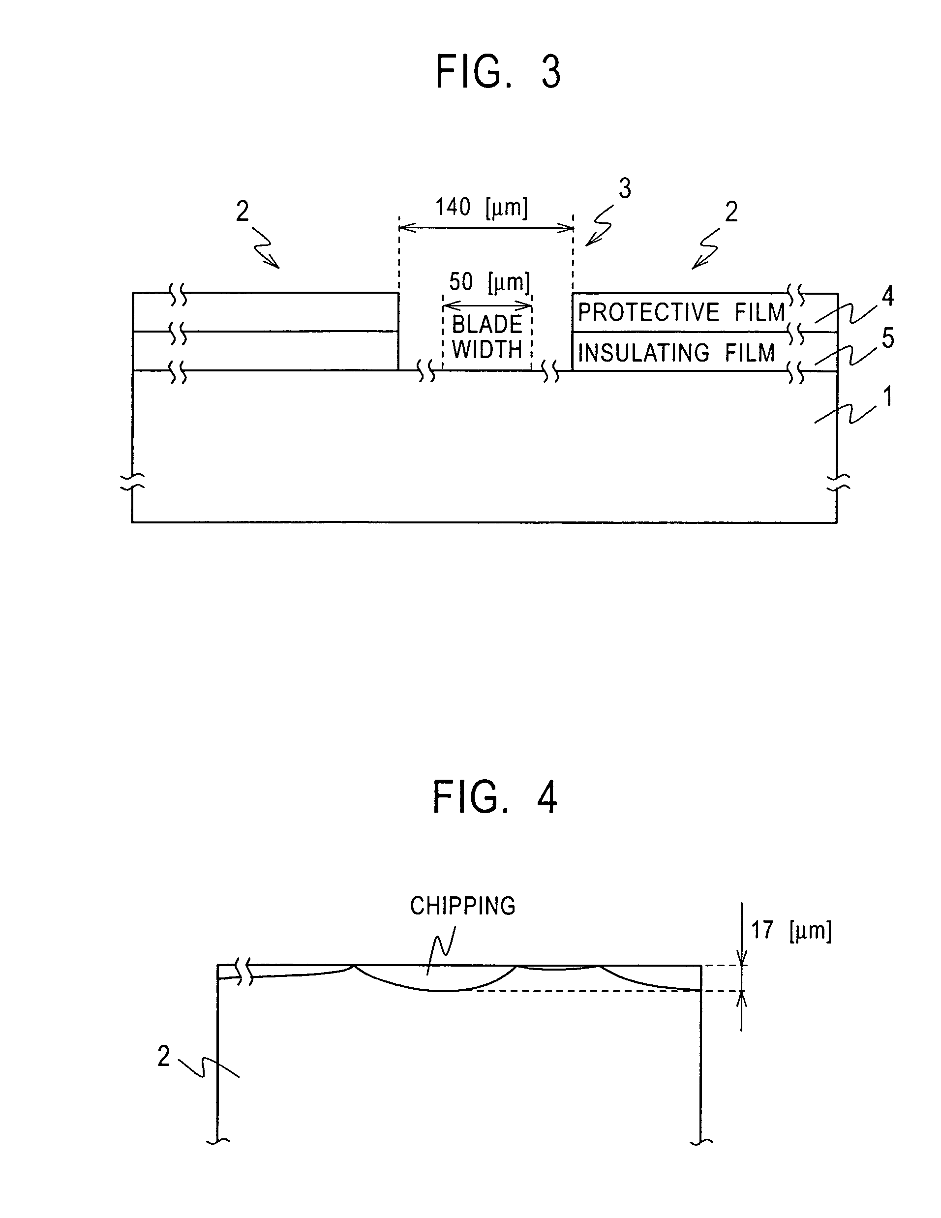
[0048]When chipping occurs at the side to which the ink is introduced, the fluid resistance in the ink...

second embodiment

2. Second Embodiment

[0062]FIG. 9 is a cross-sectional view showing the cutting region 39 between the head chips 12 applied to a second embodiment of the present invention compared to FIG. 8. In the embodiment, the grooves M are formed by removing the insulating film 30 and 33. Since the embodiment has the same structure as the first embodiment except for the steps to form the grooves M, a duplicated explanation will be omitted.

[0063]In the embodiment, the thermal oxide film 21 is not formed on the portions for forming the grooves M on the silicon wafer 40. The insulating interlayer 24 on the portions for forming the grooves M is removed during forming of the contact holes in the insulating interlayer 24. The insulating film 33 on the portions for forming the grooves M is also removed during exposing of the lands. Accordingly, the grooves M formed in this embodiment are shallower than those in the first embodiment.

[0064]According to the structure of the second embodiment, forming the...


PUM


Abstract

The present invention is applicable to, for example, a thermal printing head to form shallow grooves M by removing the insulating films 21, 24, 30, and 33 along at least the rows of the energy transducers.

Description

BACKGROUND OF INVENTION[0001]The present invention relates to liquid-ejecting heads, liquid-ejecting apparatuses, and methods for manufacturing liquid-ejecting heads, and relates to, for example, a thermal printing head. According to the present invention, insulating films on wafers are removed to form shallow grooves along at least rows of energy transducers. In this manner, the grooves can prevent various types of damage due to cracking and chipping even during high-speed dicing.[0002]In printers provided with printing heads ejecting ink droplets, energy transducers convert electric energy into energy for ejecting ink. Heating devices are used as the energy transducers for thermal printing heads.[0003]In thermal printing heads, heating devices heat ink contained in ink chambers to generate bubbles, and the ink droplets are ejected from nozzles by the pressure of bubbling.[0004]In such a printing head, heating devices and a driving circuit are integrated densely on a semiconductor ...

Claims


Application Information

Patent Timeline
Patent Type & Authority Patents(United States)
IPC IPC(8): B41J2/05B41J2/16
CPCB41J2/1603B41J2/1635B41J2/01B41J2/05B41J2/16
Inventor TOMITA, MANABU
Owner SONY CORP
Why Eureka
Try Eureka