

Wind power electric device and method
a technology of electric devices and wind power, applied in the direction of electric generator control, renewable energy generation, greenhouse gas reduction, etc., can solve the problems of long time-consuming and laborious, wind power has encountered difficulties in successfully competing economically with other energy sources, and the total production of electric power is still very marginal, so as to facilitate the use of motor functions
Inactive Publication Date: 2006-10-24
VERTICAL WIND AB
View PDF24 Cites 53 Cited by
- Summary
- Abstract
- Description
- Claims
- Application Information
AI Technical Summary
Benefits of technology
"The invention is a wind-power unit that uses a special cable winding and a vertical shaft wind turbine. This design allows for higher efficiency and better performance in winds of high speed. The use of the special winding has eliminated limitations that previously prevented the use of vertical shaft wind turbines as a practical alternative. The wind-power unit is designed to be more economical, efficient, and reliable than conventional wind-power units. It can generate more energy from wind and has a longer service life. The technical effects of the invention include improved efficiency, reliability, and cost-effectiveness."
Problems solved by technology
However wind power has encountered difficulties in successfully competing economically with other energy sources for the production of electric power.
The use of wind power for this purpose has long been limited to the supply of local energy and experimental plants.
Although the commercial production of electric energy based on wind power has gained ground in recent decades its total production of electric power is still very marginal.
However, these have not yet been used commercially and remain at the design stage although a few have been realized as experimental plants.
A decisive reason for wind turbines with vertical shafts not being favoured is that the output cannot be controlled by simply turning the turbine blade.
This limitation prevents the energy available in winds of high velocity from being exploited.
Added to other drawbacks such as low ratio between the peripheral speed of the turbine and the wind velocity and low power coefficient, i.e. the ratio between useful power and theoretical wind power, this has meant that turbines with vertical shafts have not hitherto been considered a realistic alternative.
However wind turbines with horizontal shafts also have a number of drawbacks.
The generator must either be arranged high up in the mast, in the hub of the turbine, which makes the construction expensive, or an angle gear must be arranged in the hub which also involves expense, as well as incurring losses in efficiency.
Method used
View moreImage
Smart ImageViewing Examples

Examples
second embodiment
[0065]FIG. 5 is a cross section through a turbine blade in a wind-power unit in accordance with the invention.
first embodiment
[0066]FIG. 4 is a cross section through a turbine blade in a wind-power unit in accordance with the invention.
[0067]FIG. 6 is a diagram illustrating how several units are combined to form a wind-power plant.
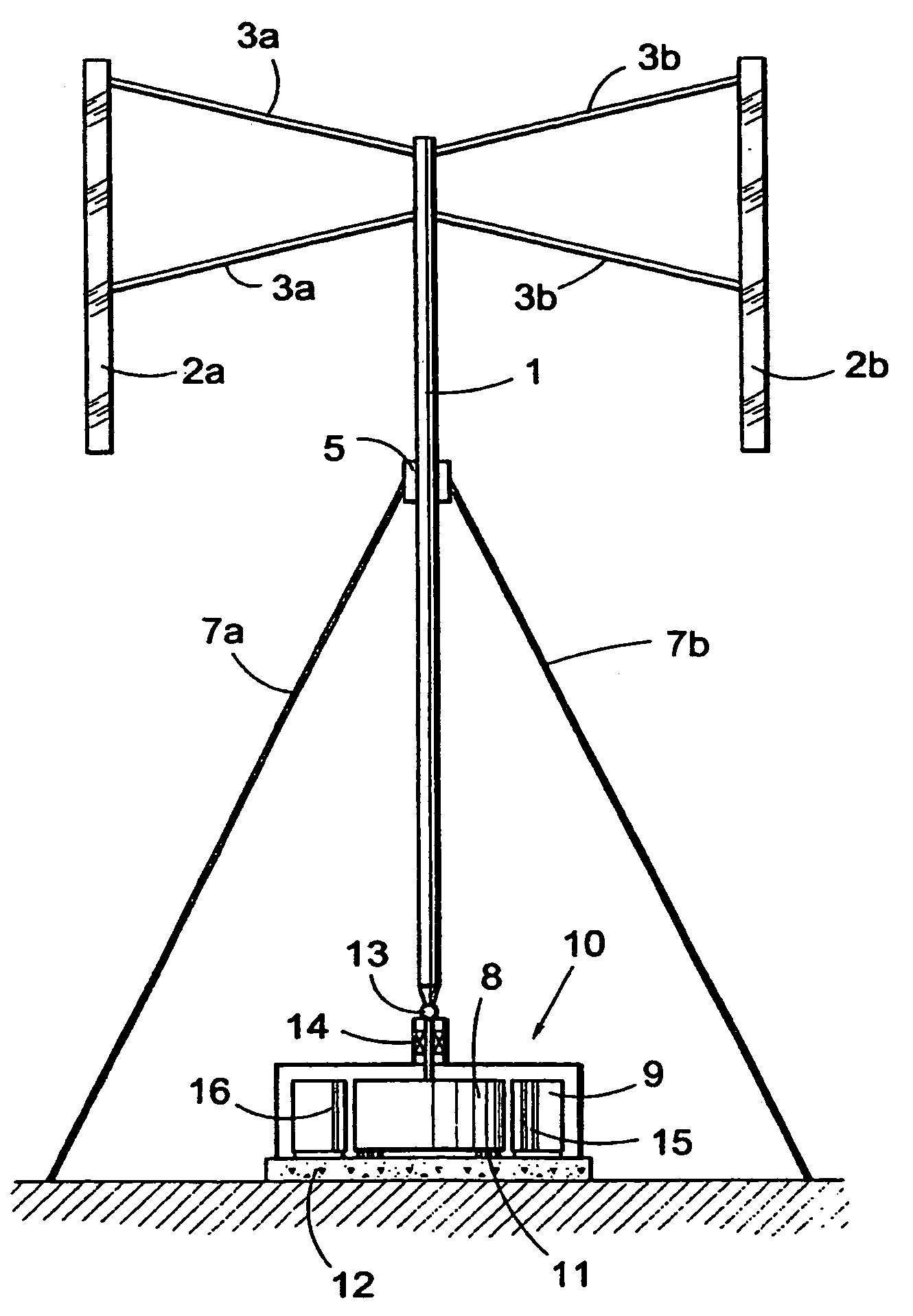
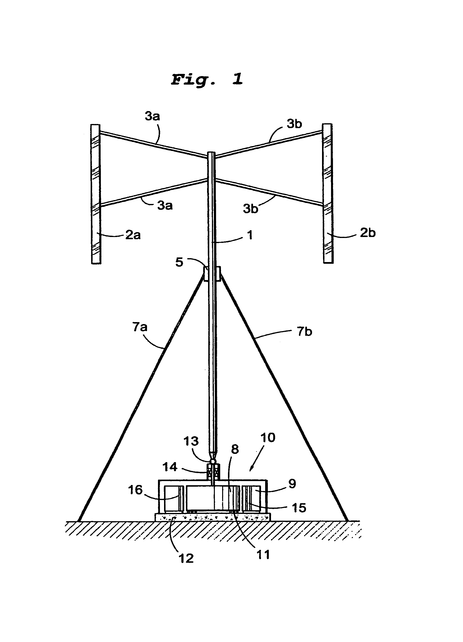
[0068]FIG. 7 illustrates in perspective a second embodiment of the wind-power unit in accordance with the invention.
third embodiment
[0069]FIG. 8 illustrates a view from the side of a wind-power unit in accordance with the invention.
[0070]FIG. 9 illustrates a wind-power plant in accordance with the invention located at sea.
[0071]FIG. 10 shows an alternative example of rectification.
Login to View More PUM
 Abstract
A wind-power unit has a wind turbine has an electric generator connected to the wind turbine. The stator of the generator has a winding formed of a high-voltage cable having a core of conducting material, a first layer of semiconducting material surrounding the core, an insulating layer of solid material surrounding the first layer, and a second layer of semiconducting material surrounding th solid insulation. The wind turbine has a plurality of turbine blades running vertically and being connected to a turbine shaft. The generator is arranged at the lower end of the turbine shaft. A wind-power plant; the use of a wind-power unit; and a method of generating electric power are described.
Description
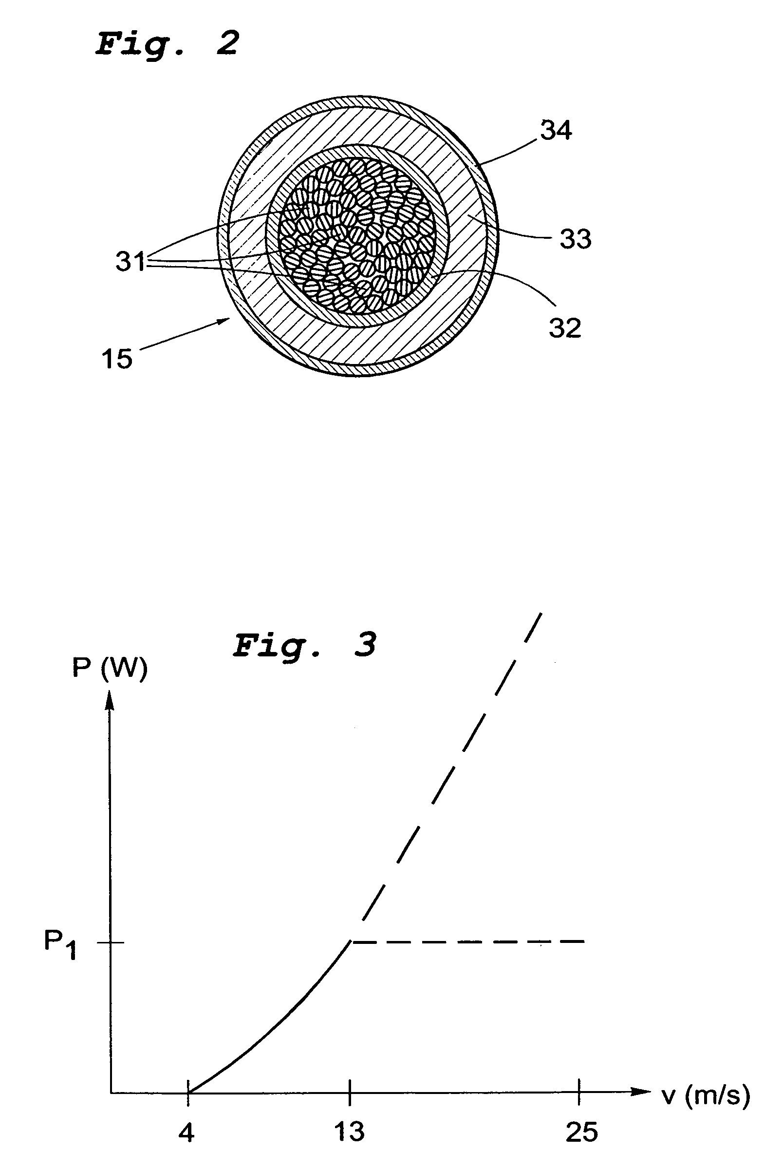
TECHNICAL FIELD[0001]A first aspect of the present invention relates to a wind-power unit of the type comprising a wind turbine and an electric generator connected to the wind turbine, the stator of the generator having a winding comprising a high-voltage cable, said cable comprising a core of conducting material, a first layer of semiconducting material surrounding the core, an insulating layer of solid material surrounding the first layer, and a second layer of semiconducting material surrounding the insulating layer.[0002]A second aspect of the invention relates to a wind-power plant comprising a plurality of wind-power units in accordance with the invention.[0003]A third aspect of the invention relates to the use of the claimed wind-power unit for producing electric current.[0004]A fourth aspect of the invention, finally, relates to a method of generating electric power wherein a wind turbine and an electric generator are arranged connected together and the stator of the generat...
Claims
Login to View More Application Information
Patent Timeline
 Patent Type & AuthorityPatents(United States)
IPC IPC(8): F03D7/06H02K3/40F03D3/00
CPCF03D3/005F05B2240/214F05B2240/95F05B2240/96Y02E10/74Y10S174/20Y02E10/727
InventorBERNHOFF, HANSLEIJON, MATS
OwnerVERTICAL WIND AB