System and method for measuring negative bias thermal instability with a ring oscillator

a technology of negative bias and thermal instability, which is applied in the testing/measurement of individual semiconductor devices, instruments, semiconductor/solid-state devices, etc., can solve the problems of affecting the performance the trade-off between performance and the lifetime of the integrated circuit, and the reliability and degradation issues of the conventional integrated circui

Inactive Publication Date: 2006-10-24
META PLATFORMS INC
View PDF6 Cites 23 Cited by
  • Summary
  • Abstract
  • Description
  • Claims
  • Application Information

AI Technical Summary

Benefits of technology

[0007]Embodiments of the present invention advantageously provide a system and method of measuring NBTI utilizing rings oscillators. The age of an associated integrated circuit, electronic device or the like may advantageously be extrapolated from the measurement of NBTI. The measurement of NBTI may also advantageously be utilized to adjust the trade-off between device performance and lifetime.

Problems solved by technology

Conventional integrated circuits suffer from numerous reliability and degradation issues.
For deep submicron (DSM) designs issues such as hot carrier injection (HCI), time dependant dielectric breakdown (TDDB), negative bias thermal instability (NBTI) and the like, increasingly affect performance of integrated circuits.
However, there is typically a tradeoff between performance and lifetime of the integrated circuit.
Changing the operating parameters to achieve increased performance typically results in an increase in stresses, such as negative bias thermal instability (NBTI).

Method used


Image

  • System and method for measuring negative bias thermal instability with a ring oscillator
  • System and method for measuring negative bias thermal instability with a ring oscillator
  • System and method for measuring negative bias thermal instability with a ring oscillator

Examples


Embodiment Construction

[0012]Reference will now be made in detail to the embodiments of the invention, examples of which are illustrated in the accompanying drawings. While the invention will be described in conjunction with these embodiments, it will be understood that they are not intended to limit the invention to these embodiments. On the contrary, the invention is intended to cover alternatives, modifications and equivalents, which may be included within the scope of the invention as defined by the appended claims. Furthermore, in the following detailed description of the present invention, numerous specific details are set forth in order to provide a thorough understanding of the present invention. However, it is understood that the present invention may be practiced without these specific details. In other instances, well-known methods, procedures, components, and circuits have not been described in detail as not to unnecessarily obscure aspects of the present invention.

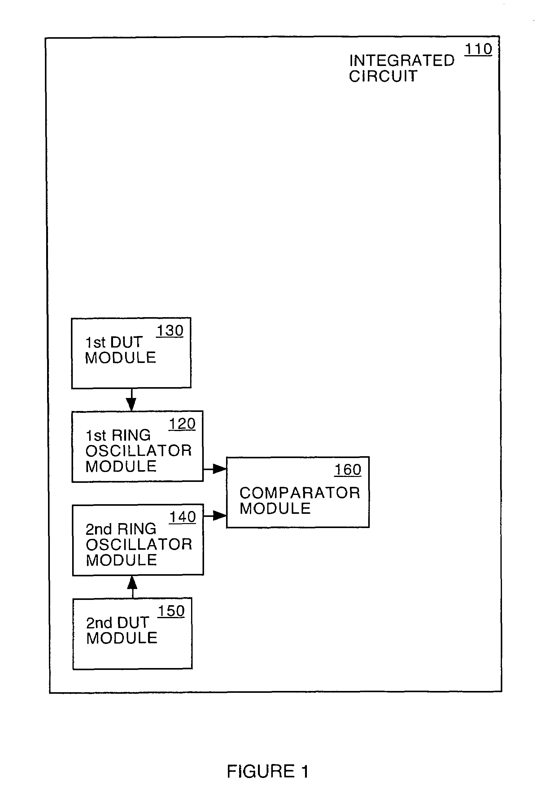
[0013]Referring to FIG. 1, a...


PUM


Abstract

An integrated circuit, in accordance with one embodiment of the present invention, includes a first device under test (DUT) module coupled to a first ring oscillator module and a second DUT module coupled to a second ring oscillator module. The first DUT module is biased such that interface traps are generated during a first mode. The generated interface traps result in a decrease in a first drive current of the first DUT module. The second device under test module is biased to maintain a reference drive current during the first mode. The operating frequency of the first ring oscillator module, during a second mode, is a function of the first drive current. The operating frequency of the second ring oscillator module, during the second mode, is a function of the reference drive current. The integrated circuit may also include a comparator module for generating an output signal as a function of a difference between the operating frequency of the first and second ring oscillator modules.

Description

CROSS-REFERENCE TO RELATED APPLICATIONS[0001]This is a continuation-in-part of U.S. patent application Ser. No. 10 / 712,847, filed Nov. 12, 2003, by Shingo Suzuki, entitled “A device Age Determination circuit,” now U.S. Pat. No. 6,903,564 U.S. patent application Ser. No. 10 / 672,793, filed Sep. 26, 2003, by Shingo Suzuki, entitled “System and Method for Measuring Transistor Leakage Current with a Ring Oscillator with Backbias Controls now U.S. Pat. No. 6,885,210,” and U.S. patent application Ser. No. 10 / 124,152, filed Apr. 16, 2002, by Shingo Suzuki, entitled “A System and Method for Measuring Transistor Leakage Current with a Ring Oscillator now U.S. Pat. No. 6,882,172,” which are incorporated herein by reference.BACKGROUND OF THE INVENTION[0002]Conventional integrated circuits suffer from numerous reliability and degradation issues. For deep submicron (DSM) designs issues such as hot carrier injection (HCI), time dependant dielectric breakdown (TDDB), negative bias thermal instabili...

Claims


Application Information

Patent Timeline
Patent Type & Authority Patents(United States)
IPC IPC(8): G01R31/02G01R31/26G01R31/28G01R31/30H01L23/544
CPCG01R31/2856G01R31/2884G01R31/3008H01L22/34G01R31/2628G01R31/2855H01L2924/3011H01L2924/0002H01L2924/00
Inventor SUZUKI, SHINGO
Owner META PLATFORMS INC
Why Eureka
Try Eureka