Auxiliary quasi-resonant dc tank electrical power converter

a converter and quasi-resonant technology, applied in the field of soft-switch converters, can solve the problems of high current stress on the main switching device, excessive number of additional active and passive components, and soft-switch inverters

Inactive Publication Date: 2006-10-24
UT BATTELLE LLC
View PDF23 Cites 28 Cited by
  • Summary
  • Abstract
  • Description
  • Claims
  • Application Information

AI Technical Summary

Benefits of technology

[0008]An auxiliary quasi-resonant DC tank (AQRDCT) power converter with fast current charging, voltage balancing (or charging), and voltage clamping circuits is provided for achieving soft-switched power conversion. The present invention is an improvement of the invention taught in U.S. Pat. No. 6,111,770, herein incorporated by reference. The present invention provides faster current charging to the resonant inductor, thus minimizing delay time of the pulse width modulation (PWM) due to the soft-switching process. The new AQRDCT converter includes three tank capacitors or power supplies to achieve the faster current charging and minimize the soft-switching time delay. The new AQRDCT converter further includes a voltage balancing circuit to charge and discharge the three tank capacitors so that additional isolated power supplies from the utility line are not needed. A voltage clamping circuit is also included for clamping voltage surge due to the reverse recovery of diodes.

Problems solved by technology

In spite of their advantages of lower EMI, dv / dt, and switching losses, these soft switching inverters have common problems compared to the resonant link inverters and traditional hard-switching inverters: (1) excessive number of additional active and passive components; (2) high current stress on the main switching devices, and (3) poor reliability.
The inverter switching devices are switched on and off at zero voltage instants of the resonant dc link, thus achieving lossless switching.
However, the ACRDCL converter has some disadvantages, such as, high voltage stress across the inverter switches and continuous resonant operation of the dc link.

Method used


Image

  • Auxiliary quasi-resonant dc tank electrical power converter
  • Auxiliary quasi-resonant dc tank electrical power converter
  • Auxiliary quasi-resonant dc tank electrical power converter

Examples


Embodiment Construction

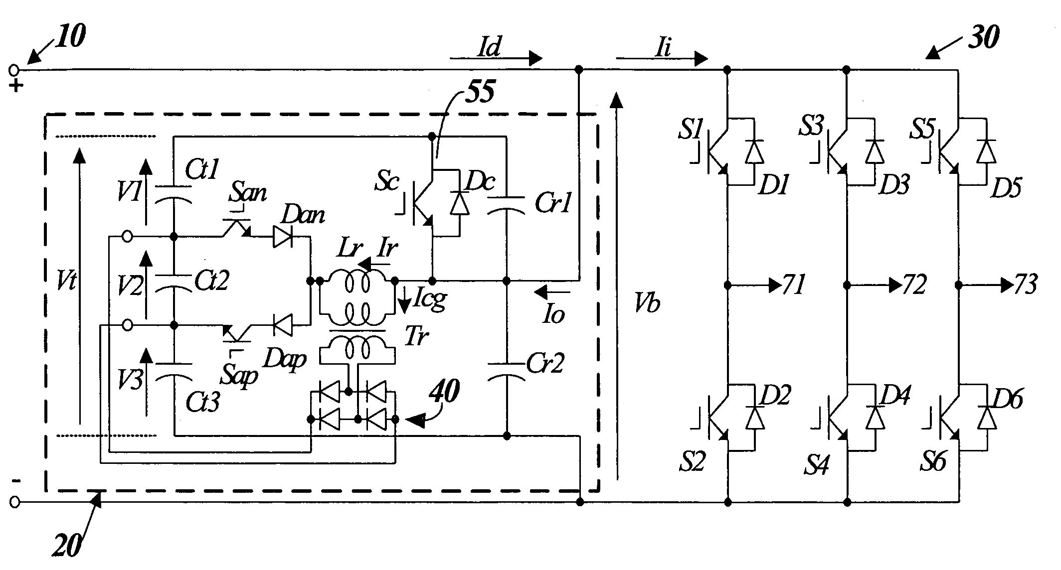
[0024]An auxiliary quasi-resonant dc tank (AQRDCT) circuit is taught as an improvement of U.S. Pat. No. 6,111,770 as shown in FIG. 8. The AQRDCT is employed to provide a quasi-resonant or resonant dc bus across the converter without transmitting real power and carrying dc current. Moreover, such an AQRDCT circuit has no problems of voltage clamping and balancing and is capable of providing opportunity for soft-switching at both ac-to-dc power conversion stage and dc-to-ac conversion stage of an ac-to-ac converter, thus making the converter circuit more compact and efficient. In addition, the AQRDCT inverter has minimum component count and minimum changes to the traditional hard-switching inverters.

[0025]The AQRDCT inverter provides a novel alternative to the existing soft-switching topologies, has been proven of concept in a 10 kW prototype, and has been put into practical use in electric bus drives (100 kW). The AQRDCT inverter includes an auxiliary resonant tank circuit which prov...


PUM


Abstract

An auxiliary quasi-resonant dc tank (AQRDCT) power converter with fast current charging, voltage balancing (or charging), and voltage clamping circuits is provided for achieving soft-switched power conversion. The present invention is an improvement of the invention taught in U.S. Pat. No. 6,111,770, herein incorporated by reference. The present invention provides faster current charging to the resonant inductor, thus minimizing delay time of the pulse width modulation (PWM) due to the soft-switching process. The new AQRDCT converter includes three tank capacitors or power supplies to achieve the faster current charging and minimize the soft-switching time delay. The new AQRDCT converter further includes a voltage balancing circuit to charge and discharge the three tank capacitors so that additional isolated power supplies from the utility line are not needed. A voltage clamping circuit is also included for clamping voltage surge due to the reverse recovery of diodes.

Description

CROSS-REFERENCE TO RELATED APPLICATIONS[0001]This application claims priority to U.S. Provisional Patent Application 60 / 630,840 filed Nov. 24, 2004, and is related to U.S. Pat. No. 6,111,770, issued Aug. 29, 2000, both herein incorporated by reference.STATEMENT REGARDING FEDERALLY SPONSORED RESEARCH[0002]This invention was made with United States Government support under Contract No. DE-AC05-00OR22725 between the United States Department of Energy and U.T. Battelle, LLC. The United States Government has certain rights in this invention.FIELD OF THE INVENTION[0003]This invention relates to soft-switching converters, and more particularly to an auxiliary quasi-resonant dc tank based converter to achieve soft and essentially lossless switching for power conversion.BACKGROUND OF THE INVENTION[0004]Soft switching technique has been used in power converters to reduce switching losses and alleviate electromagnetic interference (EMI). At present, there are two main topologies of soft switch...

Claims


Application Information

Patent Timeline
Patent Type & Authority Patents(United States)
IPC IPC(8): H02M7/5387H02M1/06H02M7/537H02M7/48
CPCH02M7/4826
Inventor PENG, FANG Z.
Owner UT BATTELLE LLC
Why Eureka
Try Eureka