Optical disk recorder optimizing laser power for initial writing and overwriting

a laser power and optical disk technology, applied in the field of optical disk recording methods and apparatuses, can solve the problems of poor recording quality and detarioration of recording quality, and achieve the effect of fine control of writing power and improving recording quality

Active Publication Date: 2006-10-24
YAMAHA CORP
View PDF10 Cites 1 Cited by
  • Summary
  • Abstract
  • Description
  • Claims
  • Application Information

AI Technical Summary

Benefits of technology

[0013]According to still another mode, the inventive method further comprises the steps of memorizing locations of the non-recorded area and the recorded area throughout the recordable area, and further memorizing a number of the overwriting operations applied to the recorded area. In such a case, the step of controlling may adjust the actual writing power of the optical beam irr

Problems solved by technology

With respect to CD-RW, however, there may be a case where an overwriting characteristic is present and the optimal writing power which has been determined by the γ method should not necessarily be the optimal value for

Method used


Image

  • Optical disk recorder optimizing laser power for initial writing and overwriting
  • Optical disk recorder optimizing laser power for initial writing and overwriting
  • Optical disk recorder optimizing laser power for initial writing and overwriting

Examples


first embodiment

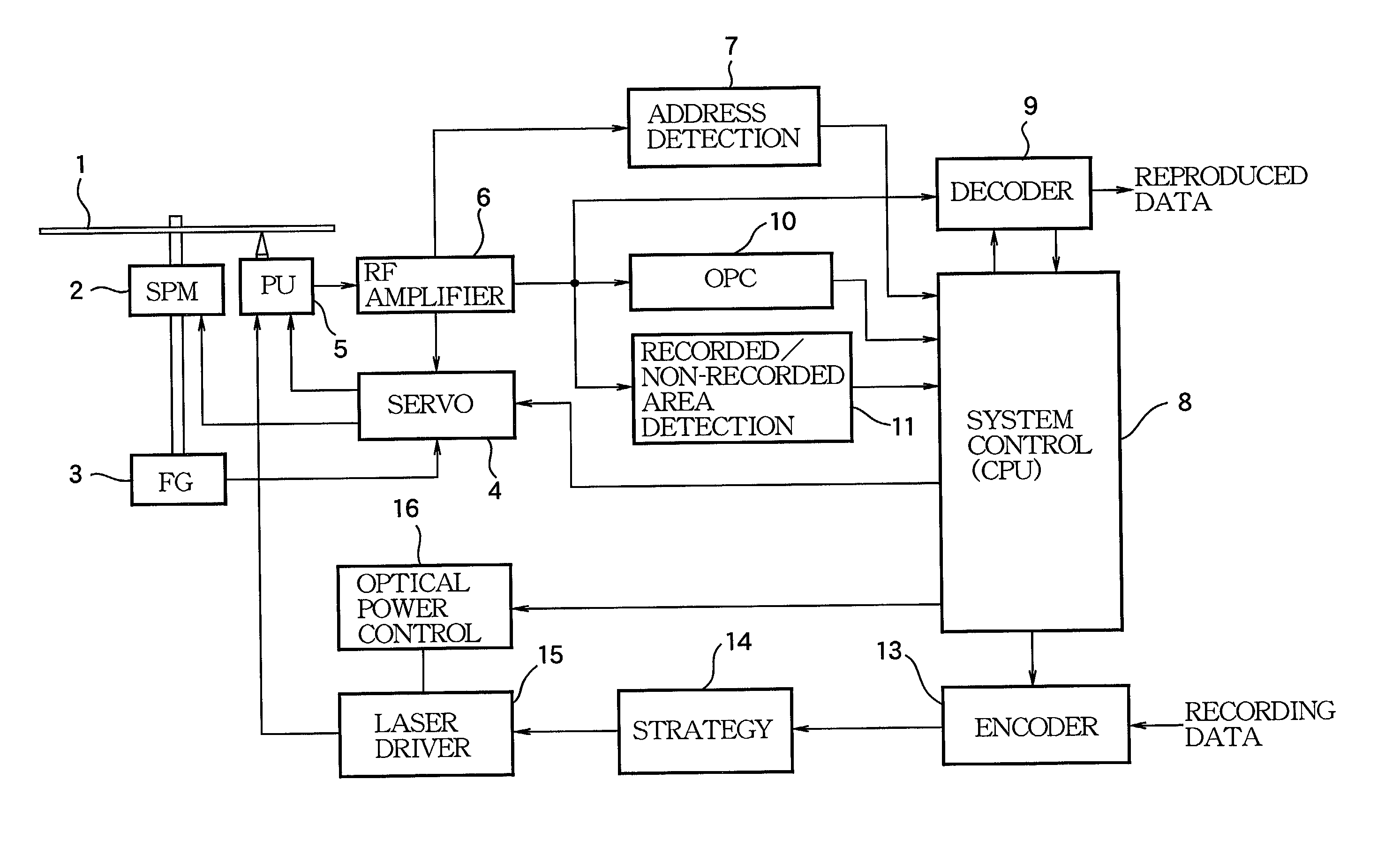
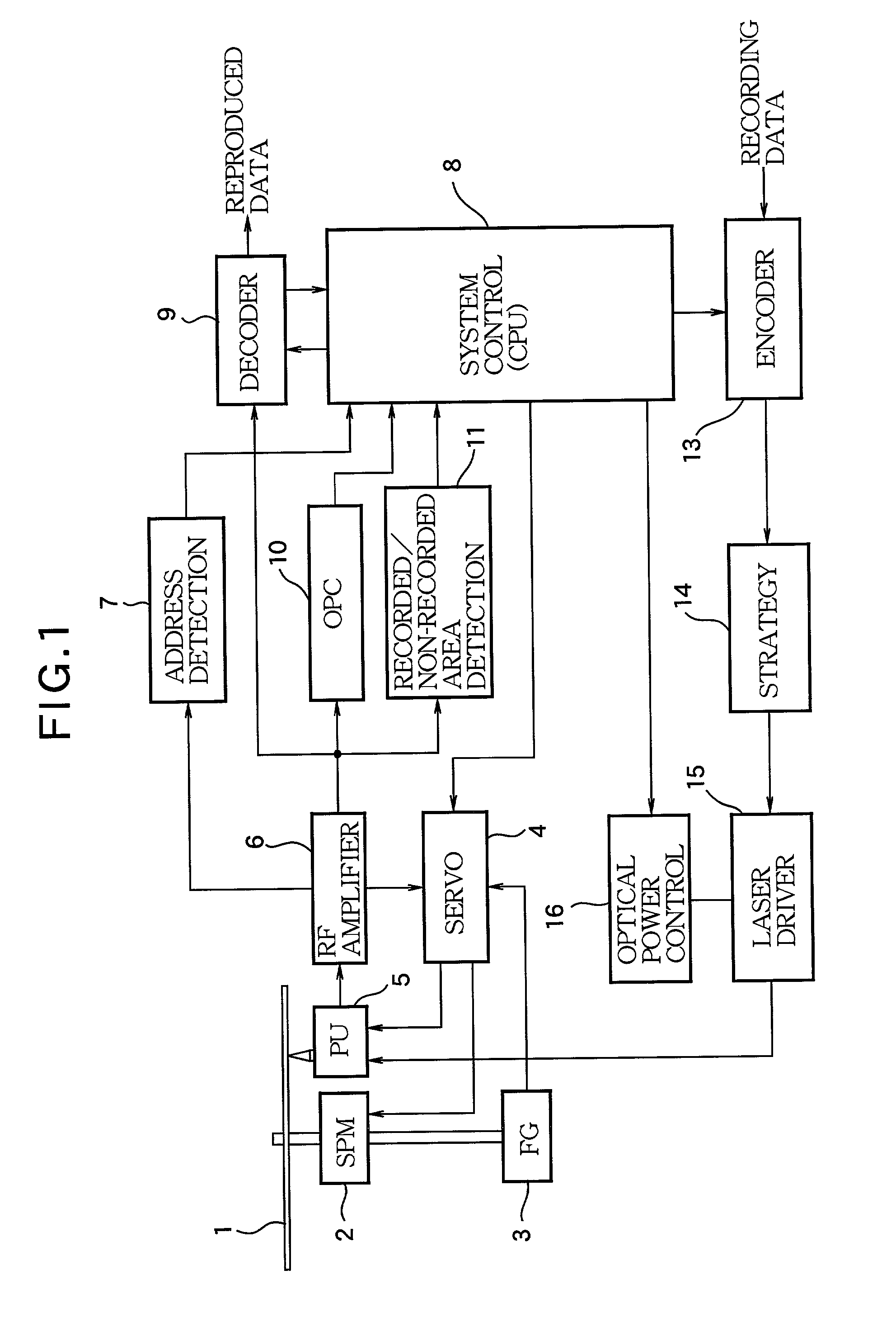
[0024]Preferred embodiments of the invention will now be described with reference to the accompanying drawings. FIG. 1 is a block diagram showing the structure of the essential portion of an optical disk recording apparatus according to the invention.

[0025]An optical disk 1 is of an overwritable type such as CD-RW, and has a spiral track in a one-stroke drawn form from the innermost periphery of a recording area to the outermost periphery. In this structure, a linear recording density control signal for defining the recording linear density of data is superimposed at a constant linear density along the track. This linear recording density control signal is a wobble (Wobble) including an ATIP (Absolute Time In Pregroove) which is absolute time information in this example. The optical disk 1 is driven to rotate by a spindle motor (SPM) 2. Connected to its rotary shaft is a frequency generator (FG) 3 comprised of a Hall element or the like, and an FG pulse to be output from the frequen...

second embodiment

[0034]FIG. 4 is a block diagram showing the structure of the essential portion of an optical disk recording apparatus according to the invention. Same reference symbols are given to those portions in FIG. 4 which are the same as the corresponding portions in FIG. 1, and redundant description on these portions will be omitted.

[0035]In this embodiment, a memory 12 is newly provided in place of the recorded / non-recorded area detection circuit 11 in FIG. 1. That is, while only the discrimination of an non-recorded area and a recorded area is done in the preceding embodiment, a recording operation time index (recording position) and the number of DOW times are stored in the memory 12 in this embodiment. That is, for a CD-RW, the optimal value of κ changes depending on the number of DOW times as shown in FIG. 5. For example, while κ=0 at the time of initial writing, the value of κ changes in such a way that κ=1.1 at DOW 1, and κ gradually decreases thereafter until DOW 10, and approaches ...

third embodiment

[0037]FIG. 7 is a block diagram showing the structure of the essential portion of an optical disk recording apparatus according to the invention. Same reference symbols are given to those portions in FIG. 7 which are the same as the corresponding portions in FIG. 1, and redundant description on these portions will be omitted.

[0038]This embodiment is to perform discrimination of initial writing and overwriting during the recording operation. Namely, the embodiment is to detect the recording state by detection means and determine a ρ value while executing the recording operation so that the writing power will be optimized.

[0039]The output of return light which is reflected back to the optical pickup 5 from the optical disk 1 during the recording operation is input to a return-light sample and hold circuit 17 and is sampled and held in accordance with a sampling pulse output from a sampling pulse generating circuit 18.

[0040]FIG. 8 shows the relationship between a recording pulse and re...


PUM


Abstract

A method is designed for recording data on a recordable area of an optical disk by irradiating thereto an optical beam having a writing power effective to write the data in the recordable area including a non-recorded area which is blank and a recorded area which is recorded with old data. The method is performed by the step of performing either of an initial writing operation or an overwriting operation for recording of new data on the optical disk, the initial writing operation irradiating the optical beam onto the non-recorded area to initially write the new data, the overwriting operation irradiating the optical beam onto the recorded area to write the new data over the old data, and the step of controlling to change the writing power of the optical beam between the initial writing operation and the overwriting operation so as to secure the recording of the new data in both of the initial writing operation and the overwriting operation.

Description

BACKGROUND OF THE INVENTION[0001]The present invention relates to an optical disk recording method and apparatus for recording information on an overwritable optical disk, such as CD-RW, DVD-RAM or DVD-RW, and more particularly relates to a method and apparatus for optical disk recording by a proper writing power at either of the time of initial writing and the time of overwriting.[0002]To compensate for a peculiarity of a disk medium, characteristics of a laser diode (LD) and variations in an optical power of LD, and to perform recording with the optimum optical power, an optical disk recording apparatus executes OPC (Optimum Power Control) to acquire the optimum power for the medium beforehand. CD-RW uses a γ method as OPC. That is, test writing of test data is carried out while changing a writing power of an LD step by step at a predetermined recording speed (linear velocity) by using a PCA (Power Calibration Area) located typically in the innermost track of an optical disk. Upon...

Claims


Application Information

Patent Timeline
IPC IPC(8): G11B7/125G11B7/0045G11B7/006G11B7/085G11B7/126
CPCG11B7/0045G11B7/006G11B7/126
Inventor YAMADA, SEIYA
Owner YAMAHA CORP
Why Eureka
Try Eureka