Water-hammer preventing unit for check valve

a technology for preventing units and check valves, which is applied in the direction of mechanical equipment, functional valve types, transportation and packaging, etc., can solve the problems of complex structure inside the valve box, high cost, and high cost, and achieve the effect of preventing water hammer with a simple structur

Inactive Publication Date: 2006-10-31
TOZEN CORP
View PDF4 Cites 4 Cited by
  • Summary
  • Abstract
  • Description
  • Claims
  • Application Information

AI Technical Summary

Benefits of technology

[0004]An object of the present invention is, for solving the problems as described above, to provide a water-hammer preventing unit capable of effectively preventing water hammer with a simple structure.

Problems solved by technology

In the check valve based on the conventional technology as described above, when a fluid flows in the reverse direction, the spring energizing the valve body to turn in the valve-closing direction prevents the valve from being quickly closed, but it is required to provide the spring guide bar as described above, a bearing guide and the like as described above to prevent water hammer, which complicates a structure inside the valve box and requires facility cost, and therefore the cost becomes disadvantageously high.
There has been proposed a valve body having a small valve hole provided thereon, but in this case it is required to additionally provide a small valve body for opening and closing the small valve hole, and the valve body is easily broken when used for a long time, which is disadvantageous.
Further there has been proposed the configuration in which a bypass conduit communicating an upstream side of the valve box flow path to the downstream side thereof is provided outside the valve box, but in this case a certain space is necessary outside the valve box, which sometimes causes troubles in installation of the valve.

Method used


Image

  • Water-hammer preventing unit for check valve
  • Water-hammer preventing unit for check valve
  • Water-hammer preventing unit for check valve

Examples


Embodiment Construction

[0010]An embodiment of the present invention is described below with reference to the related drawings.

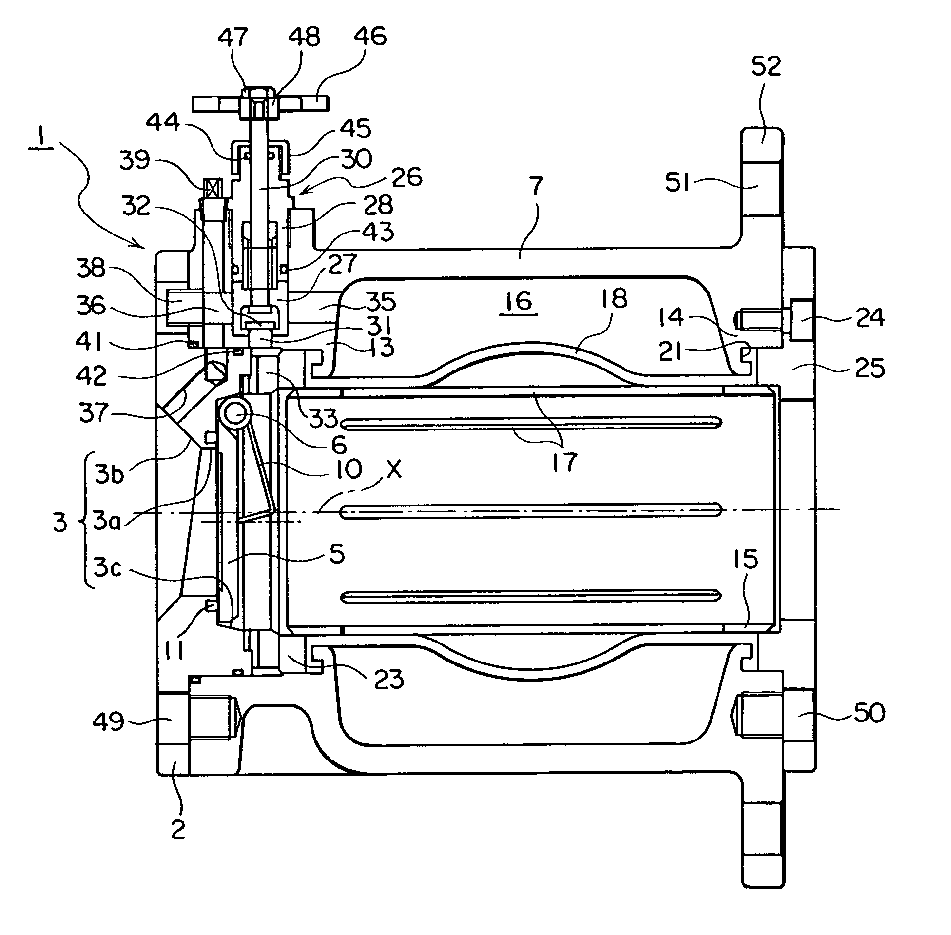
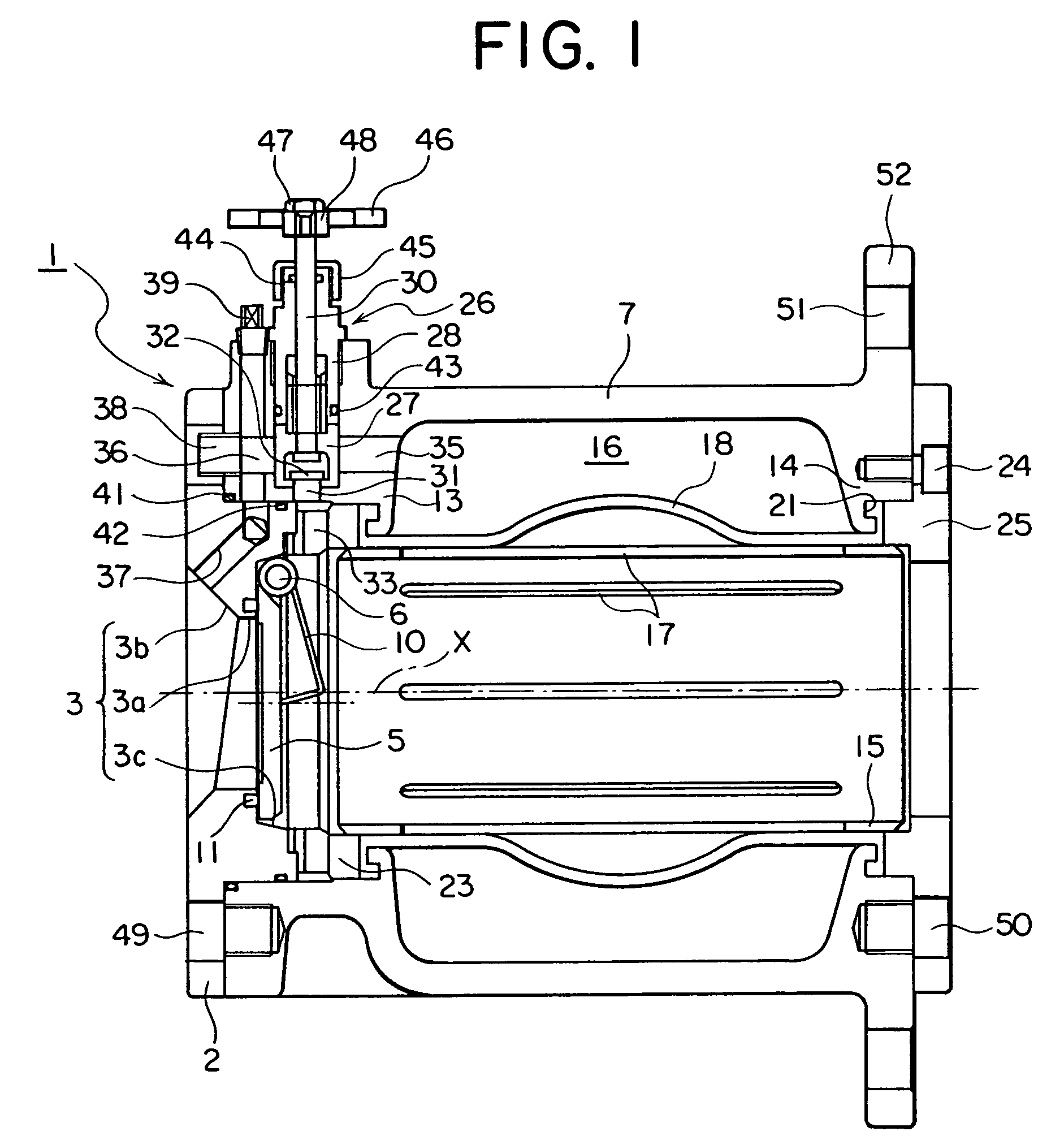
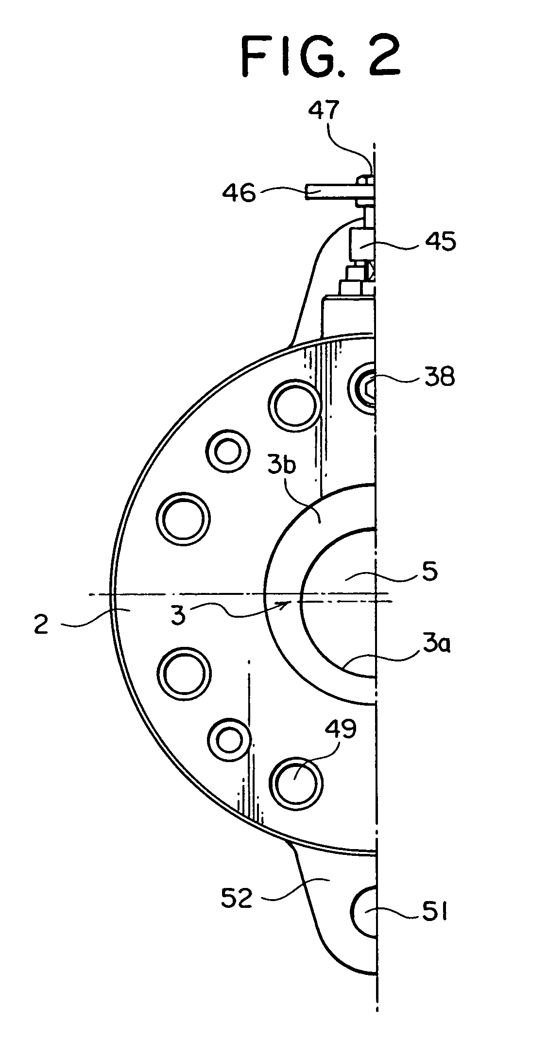
[0011]In FIG. 1, designated at reference numeral 1 is a check valve based on the swing system; and at 2 a valve body holder (valve box), and in the valve body holder, a flow path 3 with the relatively short length in the axial direction is formed, and a valve body 5 for opening and closing the flow path is rotatably supported by a valve shaft 6. Reference numeral 7 indicates a hollow and short pipe having two open edges, and an open edge section thereof is communicated to the flow path 3 in the valve body holder 2.

[0012]The flow path 3 of the valve body holder 2 has a central hole section 3a provided in the central section and slightly off downward from the center line X of the flow path 3. The central hole section 3a is formed in parallel to the center line X, and a length of the axial direction in the upstream side is shorter than that in the downstream side as shown in FIG. 1. F...


PUM


Abstract

In a water-hammer preventing unit for a check valve according to the present invention, a retainer pipe having openings at two edges thereof is provided inside a short pipe to form a circular space with the short pipe, and openings are formed on this retainer pipe. Further an elastic tube is provided on an external peripheral surface of the retainer pipe and covers the openings, and a communication path is formed between the short pipe and the valve body holder, and the communication path communicates the circular space to the flow path in the upstream side of the valve body and, when a fluid flows in the reverse direction, a portion of the fluid is accommodated from the opening into the circular space by expanding the elastic tube toward the circular space, and also flows a portion of the fluid in the said circular space to the flow path in the upstream side from the valve body.

Description

FIELD OF THE INVENTION[0001]The present invention relates to a water-hammer preventing unit for a check valve installed, for instance, in a conduit for supply water or industrial water.BACKGROUND OF THE INVENTION[0002]There are various types of check valves based on the swing system, butterfly system, lift system, or cone system. Of these check valves, a check valve based on the swing system has, as components of the basic configuration, a valve box having a flow path, and a valve body rotatably mounted on a valve shaft and functioning to open or close the flow path of the valve box. A document disclosing this type of check valve is, for instance, Japanese Patent Laid-Open Publication No. HEI 7-145870. This document discloses a check valve based on the swing system in which a valve body is energized and turned by a spring to the valve-closing direction, and the spring is wound around a spring guide bar provided at a downstream position off from the valve shaft and also in parallel t...

Claims


Application Information

Patent Timeline
Patent Type & Authority Patents(United States)
IPC IPC(8): F16K47/02F16L55/045
CPCF16K47/02F16L55/054Y10T137/7898Y10T137/7849
Inventor MUROI, AKIRAMIURA, TETSURO
Owner TOZEN CORP
Why Eureka
Try Eureka