Single track brush-based position encoder for rotating shaft

a position encoder and single track technology, applied in the field of position encoders, can solve the problems of high manufacturing cost and difficulty in fitting into small systems

Inactive Publication Date: 2006-10-31
SOMFY SAS
View PDF12 Cites 26 Cited by
  • Summary
  • Abstract
  • Description
  • Claims
  • Application Information

AI Technical Summary

Problems solved by technology

As further recognized herein, such brush-based systems require sufficient space to accommodate the three tracks, making them difficult to fit into small systems.
The positioning of the brushes is thus critical, requiring tighter tolerances between components and, thus, higher manufacturing costs.

Method used


Image

  • Single track brush-based position encoder for rotating shaft
  • Single track brush-based position encoder for rotating shaft
  • Single track brush-based position encoder for rotating shaft

Examples


Embodiment Construction

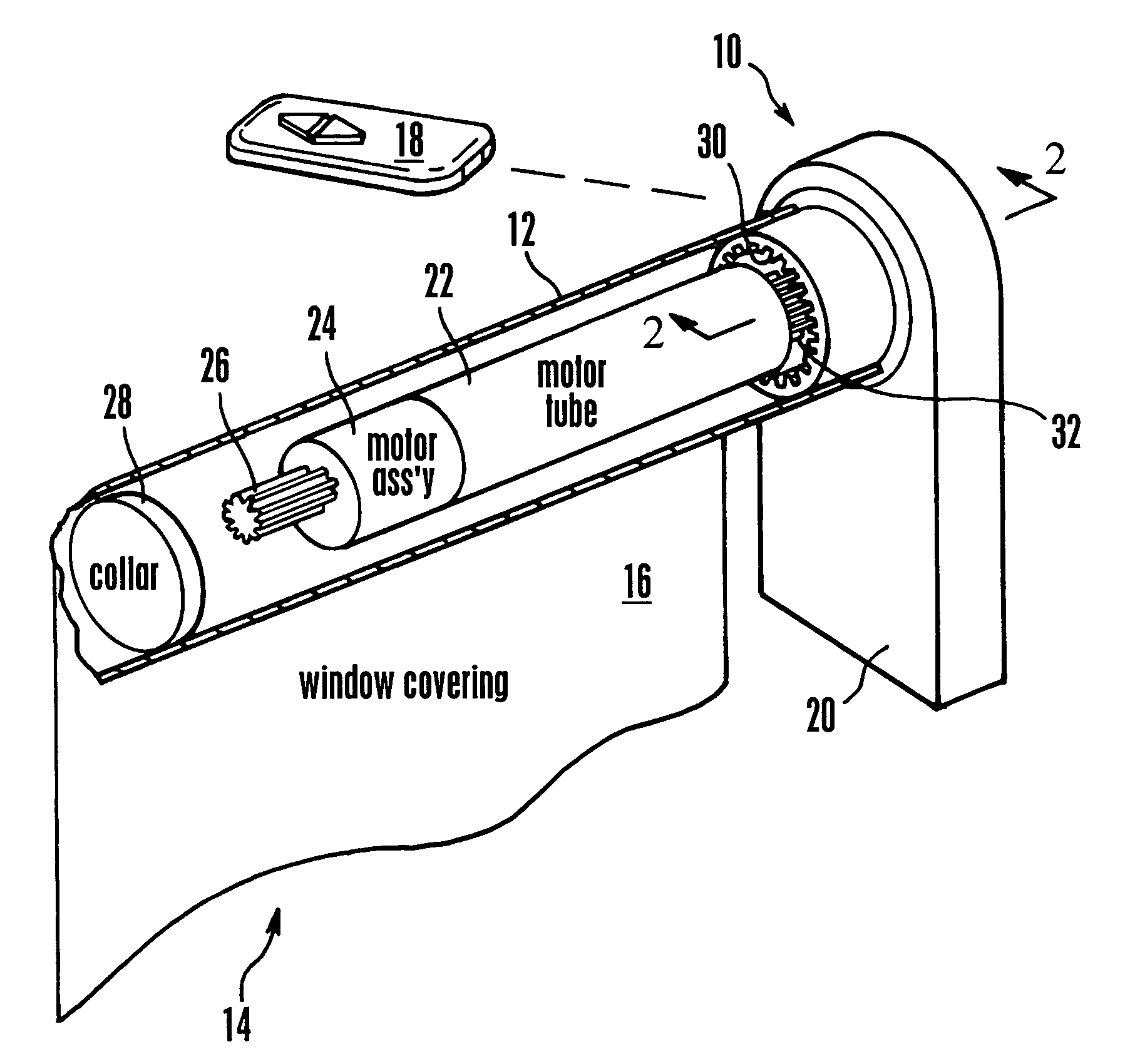
[0021]The present invention is a position encoding system for any rotating shaft, i.e., a sensor for outputting a signal representing the angular position of a rotatable object. For illustration, FIG. 1 shows the position sensor implemented in a window covering, but it is to be understood that the present position sensor as embodied in any of the implementations shown in FIGS. 3–7 may be used to output a signal representative of the angular position of any shaft (and, if desired, the angular velocity of the shaft) in accordance with present principles.

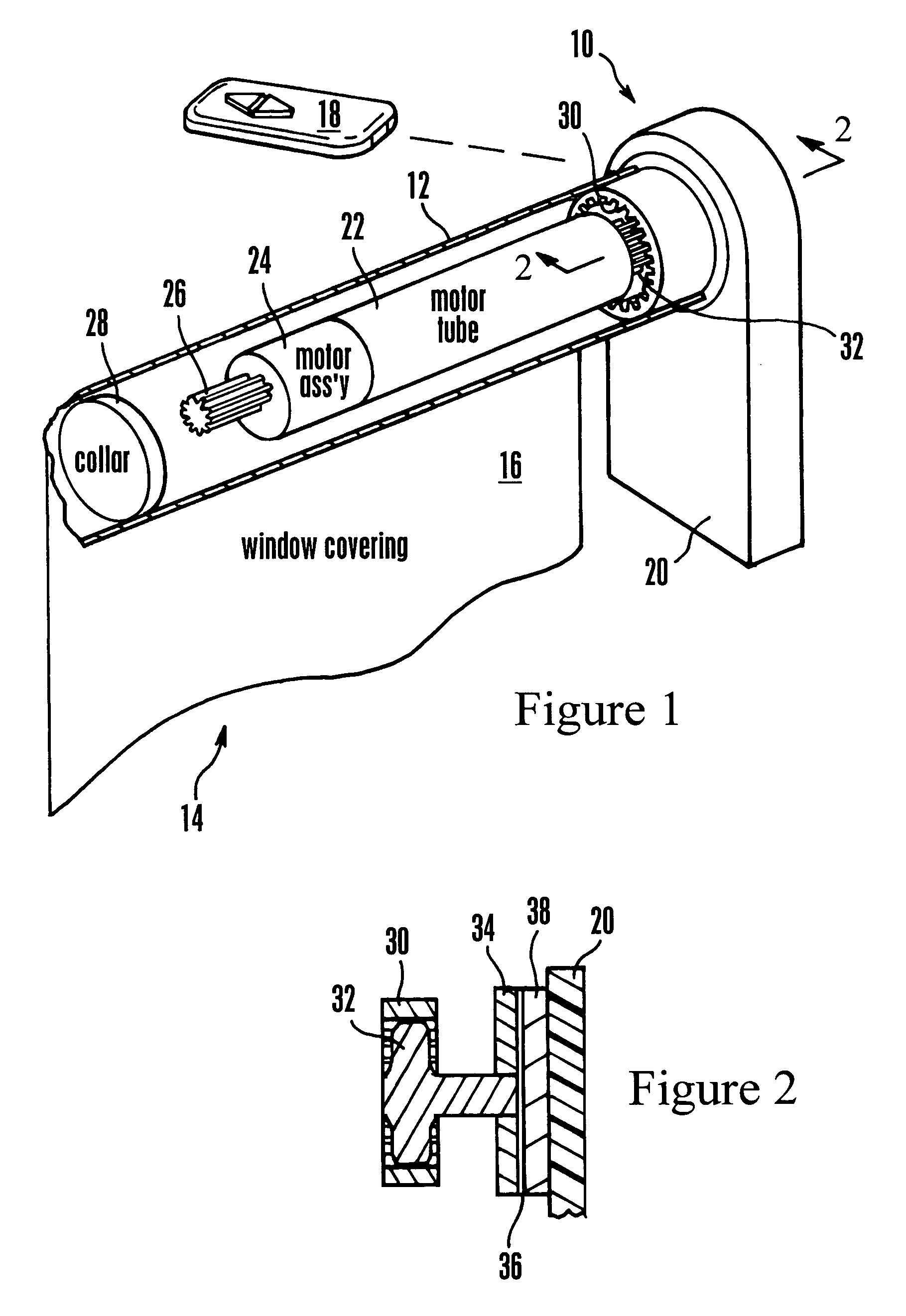
[0022]Referring initially to FIG. 1, a motorized window covering is shown, generally designated 10, that includes an actuator such as a rotatable rod 12 of a window covering 14, such as but not limited to a shade assembly having raisable (by rolling up) and lowerable (by rolling down, or unrolling) shade 16. The actuator 12 may be rotatably mounted in a head rail of the window covering 14. When the actuator 12 is rotated about its long...


PUM


Abstract

A position sensor generates a signal representative of the angular position and, if desired, angular velocity of a rotating object using only a single circular track and plural brushes that ride on the track when the object rotates. The single circular track can have plural segments, and the sensor can generate more than one signal cycle per revolution.

Description

FIELD OF THE INVENTION[0001]The present invention relates generally to brush-based position encoders for outputting the positions of rotating shafts, and more particularly for position encoders for motorized window coverings, awnings, security screens, projection screens, and the like.BACKGROUND OF THE INVENTION[0002]The present assignee has provided several systems for either lowering or raising a window covering, or for moving the slats of a window covering between open and closed positions, under control of a hand-held remote or other control device. These systems include a motor that is coupled through gears to the window covering activation mechanism. When the motor is energized in response to a user command signal, the activation mechanism moves the window covering. Such assemblies are disclosed in U.S. Pat. No. 6,433,498, incorporated herein by reference.[0003]The present assignee has also provided systems for determining the position of the window coverings based on counting...

Claims


Application Information

Patent Timeline
Patent Type & Authority Patents(United States)
IPC IPC(8): H02P1/00H02P1/22H02P1/40H02P3/00H02P3/22G01D5/25H02P7/18
CPCG01D5/25
Inventor CAVAREC, PIERRE-EMMANUELSCHROEDER, CHRISTOPHER K.
Owner SOMFY SAS
Why Eureka
Try Eureka