Picked-up-sound recording method and apparatus

Inactive Publication Date: 2006-10-31
YAMAHA CORP
View PDF7 Cites 37 Cited by
  • Summary
  • Abstract
  • Description
  • Claims
  • Application Information

AI Technical Summary

Benefits of technology

[0018]Furthermore, in each of the sound fields having the microphone and speaker, a sound-absorbing material may be disposed around or in front of the microphone and speaker. With this arrangeme

Problems solved by technology

The conventionally-known TV conference systems are designed to adjust reproduced sound volumes in a soundreproducing field irrespective of sound volumes in a soundpicking-up field, and thus can not create an effect of a “virtual conference table” achieving a feeling as if the separate sound fields were united and connected.
Therefore, the conventionally-known TV conference systems can not provide a sufficient sense of realism achieving a feel as if people

Method used


Image

  • Picked-up-sound recording method and apparatus
  • Picked-up-sound recording method and apparatus
  • Picked-up-sound recording method and apparatus

Examples


embodiment 1

[ One-channel Two-way Communication]

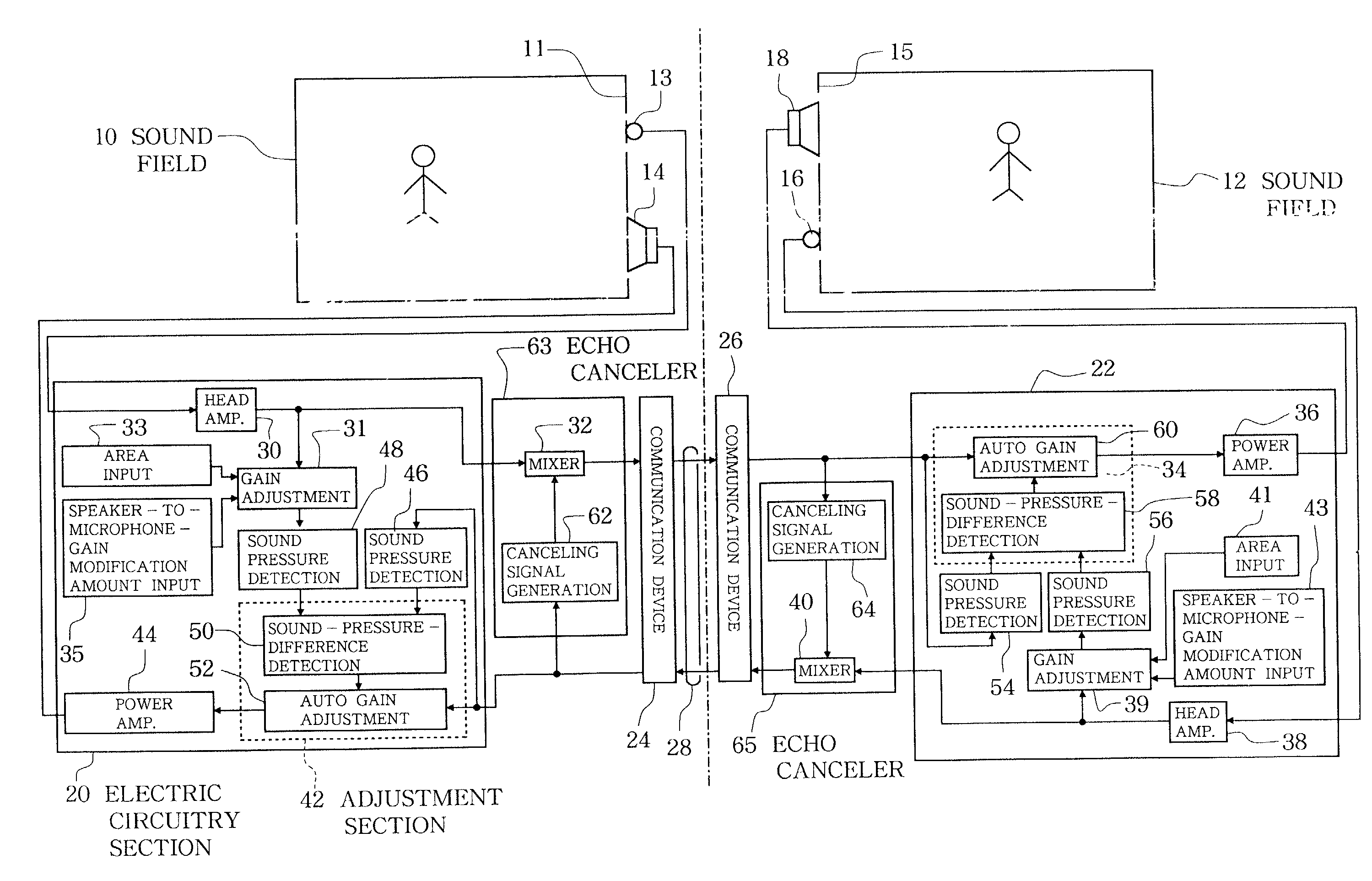
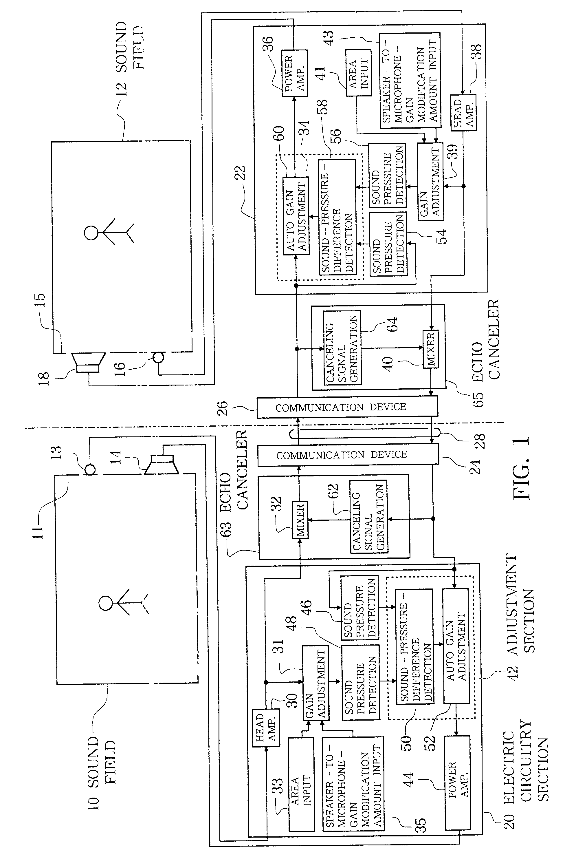
[0036]FIG. 1 is a block diagram showing an exemplary general hardware setup of an embodiment of the present invention which is designed for one-channel bidirectional or two-way communication between two separate sound fields. The first sound field 10 includes a microphone 13 and a speaker 14 provided on a wall surface 11 thereof, and similarly the second sound field 12 includes a microphone 16 and a speaker 18 provided on a wall surface 15 thereof. The microphones 13 and 16 are, for example, omni-directional microphones identical to each other in construction (i.e., of a same model), and head amplifiers 30 and 38 associated with the microphones 13 and 16, respectively, are also identical to each other in construction (i.e., of a same model). Interior shape and volume of the first and second sound fields 12 may be chosen as desired, but the wall surfaces 11 and 15 of the first and second sound fields 10 and 12 have identical or substantially identi...

embodiment 2

[ One-channel One-way Communication]

[0051]FIG. 5 is a block diagram showing an exemplary general hardware setup of another embodiment of the present invention which is designed for one-channel one-way communication between separate sound fields. In this embodiment, the first sound field 80 includes a microphone 81 provided on a single wall surface, and the second sound field 82 includes a microphone 96 and a speaker 94 provided on a single wall surface 85. Sound signal picked up by the microphone 81 of the first sound field 80 is passed via a head amplifier 84 to a transmitter device 87, from which it is transmitted via a signal transfer pathway 86 to a receiver device 90 of the second sound field 82. The sound signal received by the receiver device 90 is passed to an electric circuitry unit 92 that is constructed in a similar manner to the above-described electric circuitry unit 20 or 22 of FIG. 1. The speaker 94 and microphone 96 are connected to the electric circuitry unit 92. As...

embodiment 3

[ Plural-channel Two-way Communication]

[0058]The following paragraphs describe still another embodiment of the present invention which is constructed as a TV conference system for plural-channel two-way communication between two separate sound fields. FIG. 6 is a view schematically showing interior arrangements of the two sound fields 113 and 115, and FIG. 7 is a view showing the front of a plurality of speaker boxes 117 or 119 arranged in a matrix-like configuration. The two sound fields 113 and 115 may have any desired shape and volume, and the shapes and areas of respective one wall surfaces 114 and 116 of the two sound fields 113 and 115 are set to be the same or generally the same. In each of the two sound fields 113 and 115, the one wall surface 114 or 116 has, on its entire region, the plurality of speaker boxes 117 (119) each having identical construction with a speaker 137 (139) and microphone 141 (143) together incorporated therein in generally the same manner as illustrat...


PUM


Abstract

Sound picked up by a microphone of a first sound field is reproduced by a speaker of a second sound field, and a sound picked up by a microphone of the second sound field is reproduced by the speaker of the first sound field. Sound pressure detection section detects a sound pressure of a sound present in the second (or first) sound field picked up by the microphone of the second (or first) sound field, other than a sound reproduced by the speaker of the first (or second) sound field. Other sound pressure detection section detects a sound pressure with which the sound picked up by the microphone of the second (or first) sound field and reproduced by the speaker of the first (or second) sound field is picked up by the microphone of the first (or second) sound field. Sound-pressure-difference detection section adjusts a gain of an automatic gain adjustment section in such a manner that the two detected sound pressures assume a predetermined relationship. Thus, any sound picked up in one of the first and second sound fields can be reproduced in the other sound field with an enhanced sense of unity and connection between the two sound fields.

Description

BACKGROUND OF THE INVENTION[0001]The present invention relates to picked-up-sound reproducing methods and apparatus for picking up a sound present in one sound field and reproducing the picked-up sound in another sound field, and more particularly relates to an improved picked-up-sound reproducing method and apparatus which achieve an enhanced sense of unity (togetherness) and connection between two separate sound fields.[0002]As apparatus for picking up sounds picked up in one sound field and reproducing the picked-up sounds in another sound field, teleconference systems, such as TV conference systems, have been in actual use.[0003]The conventionally-known TV conference systems are designed to adjust reproduced sound volumes in a soundreproducing field irrespective of sound volumes in a soundpicking-up field, and thus can not create an effect of a “virtual conference table” achieving a feeling as if the separate sound fields were united and connected. Therefore, the conventionally-...

Claims


Application Information

Patent Timeline
IPC IPC(8): H04B3/20H03G3/32H04N7/15H03G5/22H04R3/02H04R5/02H04R5/027H04S1/00H04S3/00
CPCH03G3/32H03G5/22H04S1/002
Inventor HIRAI, TORUKAWAKAMI, FUKUSHISHIMIZU, YASUSHIHONJI, YOSHIKAZUIKEDA, MASAHIROTOHYAMA, MIKIO
Owner YAMAHA CORP
Why Eureka
Try Eureka