Method of predicting springback in hydroforming

Active Publication Date: 2006-10-31
TEXTRON INNOVATIONS
View PDF12 Cites 23 Cited by
  • Summary
  • Abstract
  • Description
  • Claims
  • Application Information

AI Technical Summary

Benefits of technology

[0017]It is, therefore, the principal object of the present invention to provide a method for accurately calculating springback by

Problems solved by technology

The problems in the prior methods of accurately predicting springback are numerous.
They don't include process factors; they don't consider interactions between the geometric and material factors; they in

Method used


Image

  • Method of predicting springback in hydroforming
  • Method of predicting springback in hydroforming
  • Method of predicting springback in hydroforming

Examples


Embodiment Construction

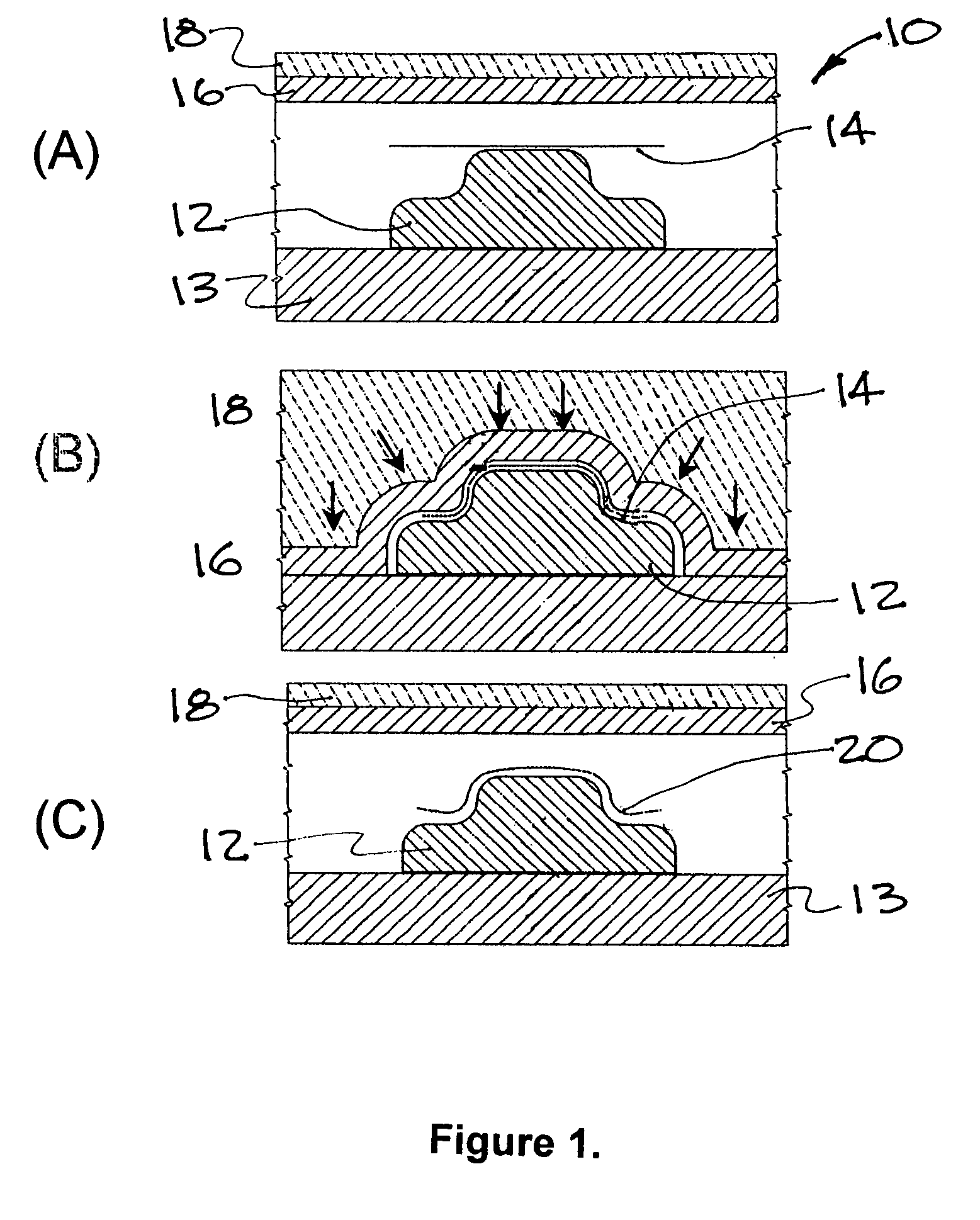
[0027]Hydroforming, sometimes referred to as fluid forming or rubber diaphragm forming, was developed in response to a need for a low cost method of producing relatively small quantities of a wide variety of sheet metal parts. The principal of forming in a typical hydropress is illustrated in FIG. 1. It symbolically illustrates a typical hydropress before the forming starts in Illustration “A”; pressure being applied on the diaphragm or bladder to form the part in Illustration “B”; and removal of the part after the pressure of the bladder is relieved in Illustration “C”. The tool 12 is placed in the hydropress 10 on a fixed table 13. A sheet metal blank 14 placed on top of the tool 12. A rubber diaphragm 16 in the “A” illustration is shown retracted with unpressurized fluid 18 positioned above the diaphragm. In Illustration “B” the fluid 18 is pressurized thus causing diaphragm 16 to extend downward forming the blank 14 around the tool 12. The high pressure fluid above that diaphrag...


PUM

PropertyMeasurementUnit
Angleaaaaaaaaaa
Pressureaaaaaaaaaa
Angleaaaaaaaaaa

Abstract

A method of determining springback in metal forming with a fluid cell press through establishing a computational formulation to determine bend angle and compensated die radius based on factors of geometry of the part being formed, material properties of the sheet material and the forming process, and computing additional iterations of springback until a specific tolerance between the formed part angle and the desired part angle are reached.

Description

BACKGROUND OF THE INVENTION[0001]1. Field of the Invention[0002]This invention relates to bending methods for forming sheet metal parts and more specifically for calculating springback when forming parts by hydroforming with a fixed die and hydraulic pressure exerted by a flexible diaphragm.[0003]2. Description of Prior Art[0004]With the advent of metal airplanes, it became necessary to find a method of forming complex sheet metal parts economically. Traditional stamping methods, also referred to as draw forming, involve high tool costs that could not be justified for the relatively small quantities of parts produced. Traditional stamping required two mating precisely aligned dies. Hydroforming, also referred to as fluid forming, involves only a single die wherein the hydraulic pressure was applied against a flexible diaphragm, which forms the sheet material against a die.[0005]Various other metal forming methods are utilized in the various industries such as a stretch press, wherei...

Claims


Application Information

Patent Timeline
IPC IPC(8): B21C1/00
CPCB21D22/10Y10S72/702
Inventor KULKARNI, PRAVINDATTA, SUBHRANGSHUVIRGINIA, MARK A.
Owner TEXTRON INNOVATIONS
Why Eureka
Try Eureka