Fence router table system

Inactive Publication Date: 2006-11-07
SOMMERS JAMES
View PDF7 Cites 4 Cited by
  • Summary
  • Abstract
  • Description
  • Claims
  • Application Information

AI Technical Summary

Benefits of technology

[0023]It is therefore an object of the present invention to provide a new and improved fence router table system which has all of the advantages of the prior art pantographs and routers of known designs and configurations and none of the disadvantages.
[0024]It is another object of the present invention to provide a new and improved fence router table system which may be easily and efficiently manufactured and marketed.
[0025]It is further object of the present invention to provide a new and improved fence router table system which is of durable and reliable constructions

Problems solved by technology

While these devices fulfill their respective, particular objectives and requirements, the aforementioned patents do not describe

Method used


Image

  • Fence router table system
  • Fence router table system
  • Fence router table system

Examples


Embodiment Construction

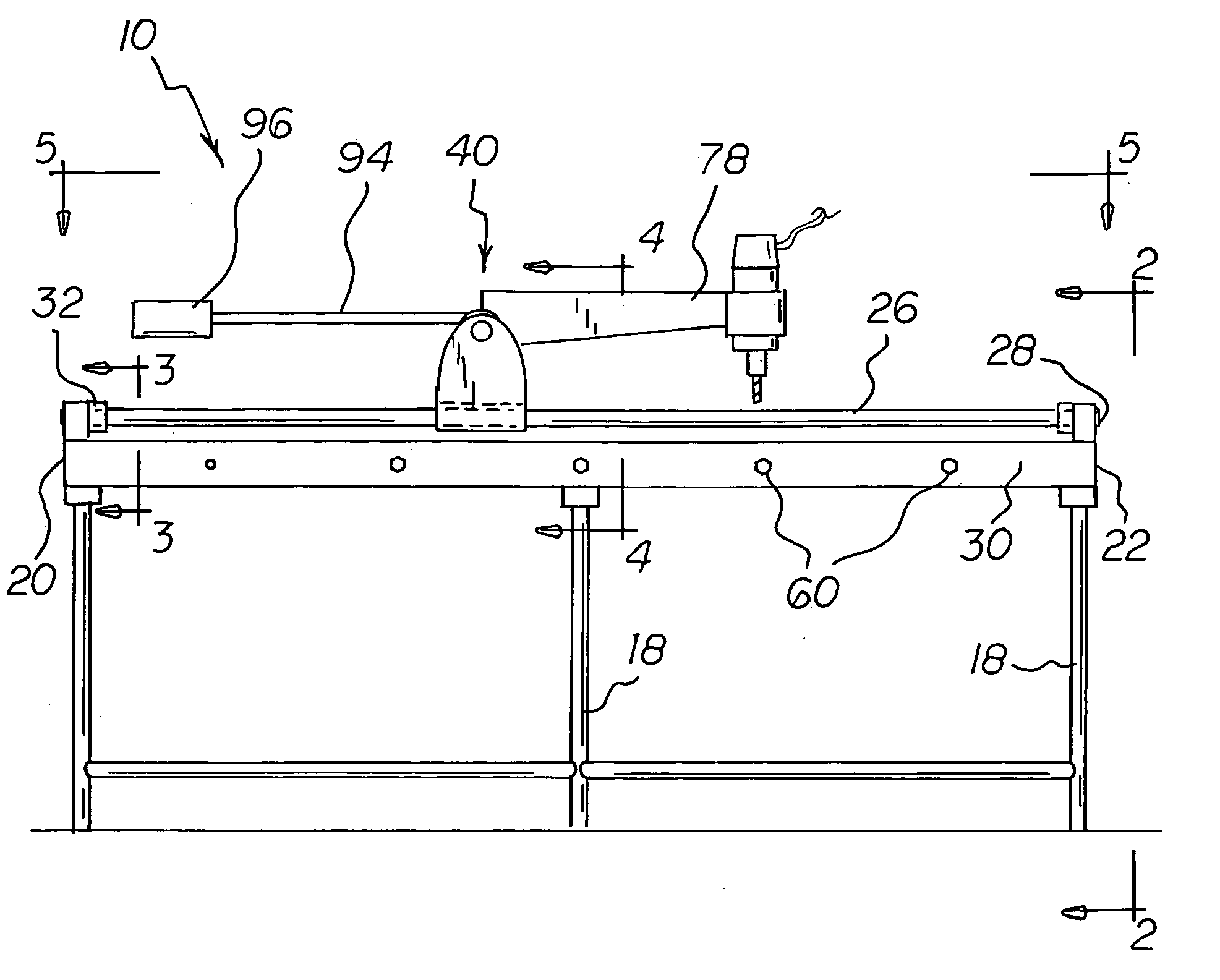
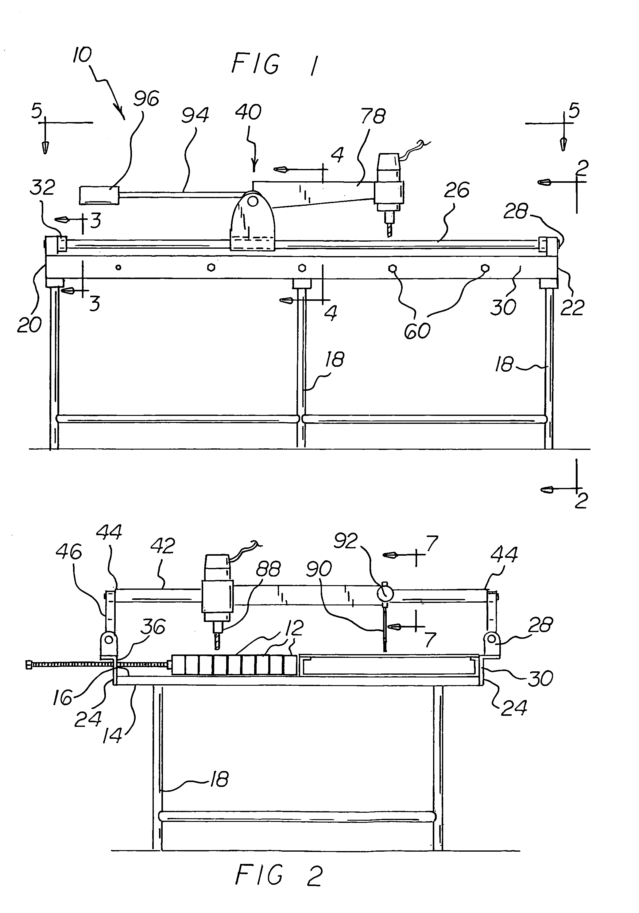
[0046]With reference now to the drawings, and in particular to FIG. 1 thereof, the preferred embodiment of the new and improved fence router table system embodying the principles and concepts of the present invention and generally designated by the reference numeral 10 will be described.

[0047]The present invention, the fence router table system 10 is comprised of a plurality of components. Such components in their broadest context include a table, a slide assembly, a pantograph, a router, and control mechanisms. Such components are individually configured and correlated with respect to each other so as to attain the desired objective.

[0048]First provided is a table 14. The table has a planar working surface 16. The working surface is in a horizontal plane. The working surface has depending legs 18. The depending legs maintain the table and working surface at a desired height. The working surface has a near side 20 and a parallel far side 22. Parallel lateral sides 24 are provided be...


PUM

PropertyMeasurementUnit
Weightaaaaaaaaaa
Heightaaaaaaaaaa

Abstract

A table with a working surface has a parallel rail on each side of the working surface. A slide assembly includes a shaft with ends and a pair of brackets. Each bracket has a hole. The holes receive the ends of the shaft. The slide assembly includes cylindrical tunnels. The tunnels slidably receive the rails. An operating assembly has primary and secondary arms. Each arm has a free exterior end and an interior portion. The interior portion is coupled to the shaft. A router is secured to, and depends from, the free end of the secondary arm. Control mechanisms include a scribe. The scribe is secured to, and depends from, the free end of the primary arm. Movement of the primary arm and scribe with respect to a template will cause corresponding movement of the secondary arm and router with respect to work pieces to be routed.

Description

RELATED APPLICATION[0001]The present application is a continuation-in-part of U.S. patent application Ser. No. 10 / 769,335 filed Jan. 30, 2004 now abandoned.BACKGROUND OF THE INVENTION[0002]1. Field of the Invention[0003]The present invention relates to a fence router table system and more particularly pertains to supporting and routing linear fence components in a safe, accurate, and efficient manner.[0004]2. Description of the Prior Art[0005]The use of pantographs and routers of known designs and configurations is known in the prior art. More specifically, pantographs and routers of known designs and configurations previously devised and utilized for the purpose of fabricating fences through conventional methods and apparatuses are known to consist basically of familiar, expected, and obvious structural configurations, notwithstanding the myriad of designs encompassed by the crowded prior art which has been developed for the fulfillment of countless objectives and requirements.[000...

Claims


Application Information

Patent Timeline
IPC IPC(8): B25H1/02B23C1/16B25H1/00B26D1/14
CPCB25H1/0021Y10T409/301232Y10T409/301568Y10T409/303416
Inventor SOMMERS, JAMES
Owner SOMMERS JAMES
Why Eureka
Try Eureka