Method and circuit for producing a control voltage for a VCO

a voltage control and control voltage technology, applied in the direction of automatic control, electrical equipment, etc., can solve the problem of difficult generation of stabilized reference values, and achieve the effect of simple circuit measurement and improved resolution

Active Publication Date: 2006-11-07
ATMEL CORP +1
View PDF5 Cites 5 Cited by
  • Summary
  • Abstract
  • Description
  • Claims
  • Application Information

AI Technical Summary

Benefits of technology

[0007]to substantially shorten the above mentioned settling time when a frequency change or a starting of the phase locked loop is required in a circuit arrangement for producing a control voltage for a voltage controlled oscillator;
[0026]According to a further preferred embodiment of the present invention two switchable capacitor (SC) amplifiers are provided, one of these amplifiers has an inverting characteristic and produces a possible, future oscillator control voltage (VC(t+1)) while the other SC amplifier has a non-inverting characteristic and produces a further possible, future oscillator control voltage (VC(t+1)). With these two amplifiers it is possible to provide two future possible oscillator control voltages in parallel already during a current counting period or sequence so that these future values are immediately available for selection for the next iterating step. In this connection it is preferred that the respective SC-amplifier produces the corresponding future oscillator control voltage VC(t+1) as a function of a past oscillator control voltage value VC(t−1) and on the basis of an actual, current control voltage value VC(t). In this embodiment of the present circuit arrangement it is possible to make the voltage increments and the voltage decrements or voltage differences dependent on the spacing of the values VC(t) and VC(t−1). In this manner it is possible to achieve an increasing resolution and precision of the control value determination as the number of iteration steps increases.

Problems solved by technology

Particularly, the generation of stabilized reference values is difficult in connection with realizing the phase locked loop in accordance with complementary metal oxide semiconductor technologies (CMOS).

Method used


Image

  • Method and circuit for producing a control voltage for a VCO
  • Method and circuit for producing a control voltage for a VCO
  • Method and circuit for producing a control voltage for a VCO

Examples


Embodiment Construction

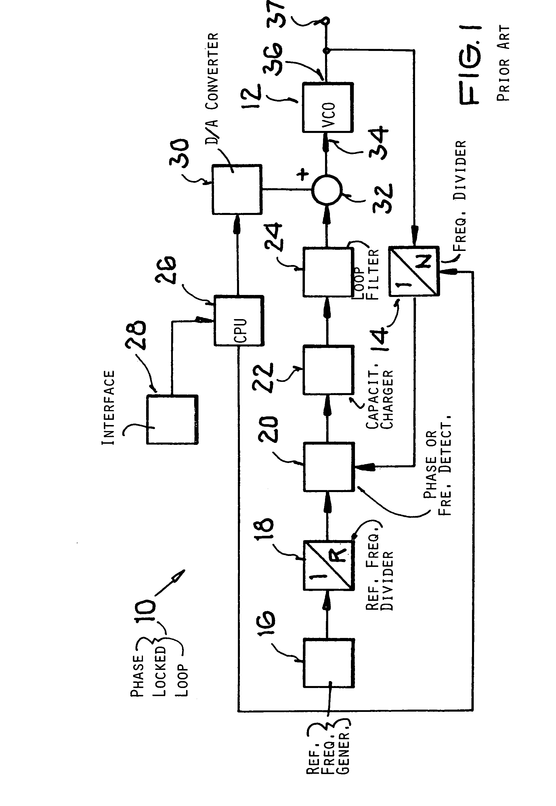
[0036]FIG. 1 shows a conventional phase locked loop 10 that produces a control voltage for a voltage controlled oscillator 12. The phase locked loop includes a programmable main frequency divider 14, a reference frequency generator 16, a reference frequency divider 18, a phase or frequency detector 20, a capacitor charging pump 22, a loop filter 24, and a control 26. The control 26 reacts to input signals supplied through an interface 28. The control 26 provides, for example, a control signal to the main frequency divider 14 and an input signal to a digital-to-analog converter 30 which supplies through a logic circuit component 32, a control voltage to an input 34 of the voltage controlled oscillator 12. The oscillator 12 has an output 36 connected to an input of the main frequency divider 14 and to a circuit node 37 which supplies the oscillator output signal to a mixing stage of a transmitter and / or a receiver.

[0037]The phase locked loop 10 functions basically as follows. The refe...


PUM


Abstract

The control voltage for a VCO (voltage controlled oscillator) is produced in a phase locked loop which in turn is controlled by a computer (40) including an integrated analog circuit (42). First the oscillator control voltage is set to a predetermined value. Then, voltage varying steps are performed. For performing these steps, the circuit includes a main frequency divider and a reference frequency divider both functioning as counters. The beginnings of the counting of each divider are synchronized with each other. The oscillator control voltage is increased by a predetermined voltage difference or increment when the reference divider completes its counting period prior to the main divider completing its counting. The oscillator control voltage is decreased by a predetermined voltage difference or decrement when the main divider finishes its counting period prior to the reference divider finishing its count.

Description

PRIORITY CLAIM[0001]This application is based on and claims the priority under 35 U.S.C. §119 of German Patent Application 103 54 522.0, filed on Nov. 14, 2003, the entire disclosure of which is incorporated herein by reference.FIELD OF THE INVENTION[0002]The invention relates to a method and circuit for producing a control voltage for a voltage controlled oscillator (VCO). Starting with a preset control voltage, a phase locked loop is used to vary the preset control voltage. The circuit arrangement is capable of presetting the initial control voltage.BACKGROUND INFORMATION[0003]European Patent Publication EP 993,122 describes a method and circuit as mentioned above. So-called phase locked loops (PLL), are used for generating, with the aid of frequency synthesizers, defined frequency signals for frequency mixers. In connection with transceiver systems it is necessary that the rated frequency of the oscillator output signal varies significantly within a short period of time. For exam...

Claims


Application Information

Patent Timeline
Patent Type & Authority Patents(United States)
IPC IPC(8): H03L7/06H03L7/00H03L7/10H03L7/187H03L7/199
CPCH03L7/10H03L7/187H03L7/199H03L7/104
Inventor HOFMANN, KARL
Owner ATMEL CORP
Why Eureka
Try Eureka