Variable hologram element, and optical device using the same

a hologram element and variable technology, applied in the field of variable hologram elements and optical devices, can solve the problem of limited light available to about 40%, and achieve the effect of increasing the amount of light and variable optical characteristics

Inactive Publication Date: 2006-11-07
OLYMPUS CORP
View PDF6 Cites 73 Cited by
  • Summary
  • Abstract
  • Description
  • Claims
  • Application Information

AI Technical Summary

Problems solved by technology

However, a problem with this liquid crystal lens arrangement 901 is that the amount of light available is limited to about 40% due to the presence of the polarizing plate 902.

Method used


Image

  • Variable hologram element, and optical device using the same
  • Variable hologram element, and optical device using the same
  • Variable hologram element, and optical device using the same

Examples


Embodiment Construction

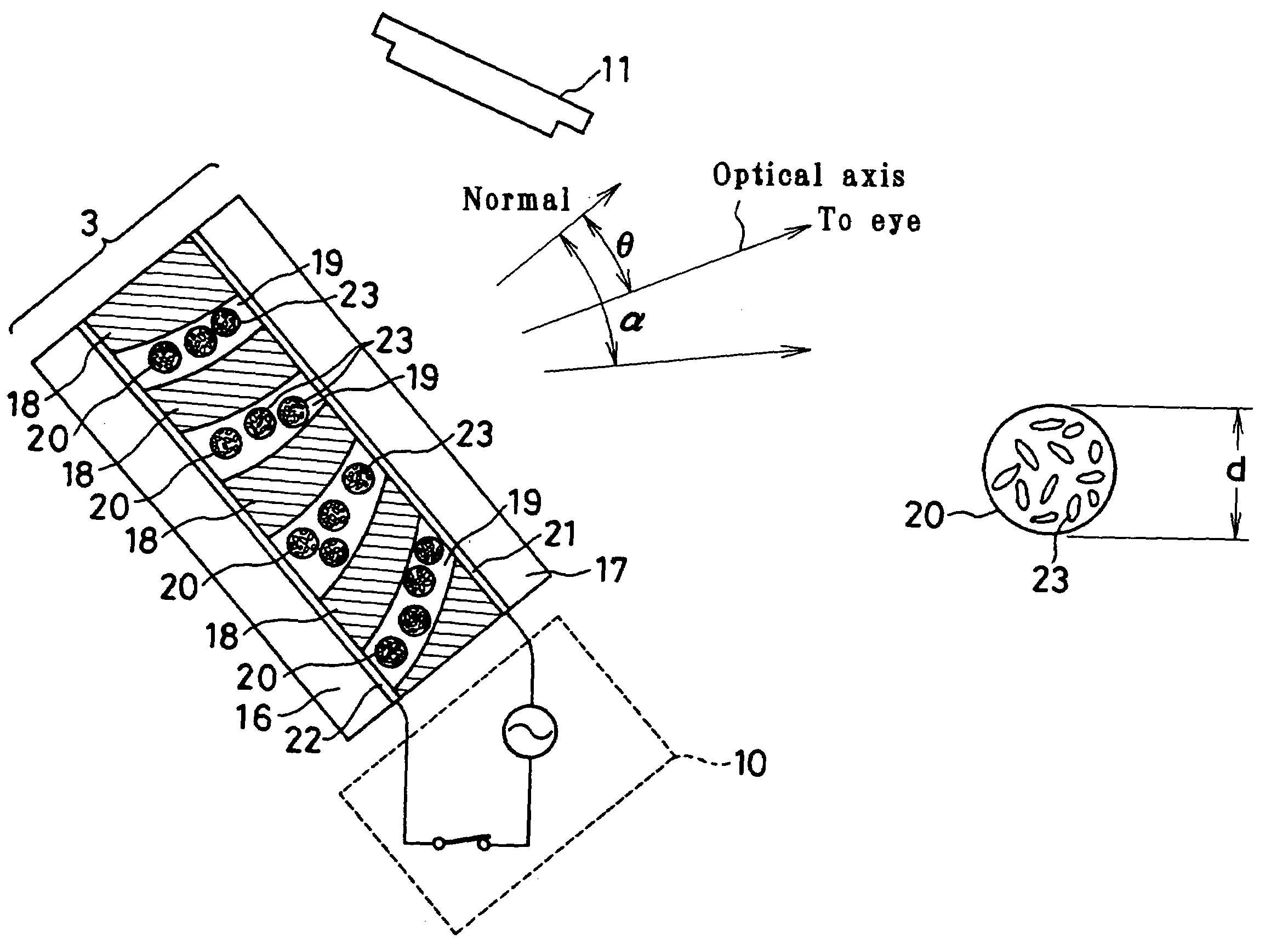
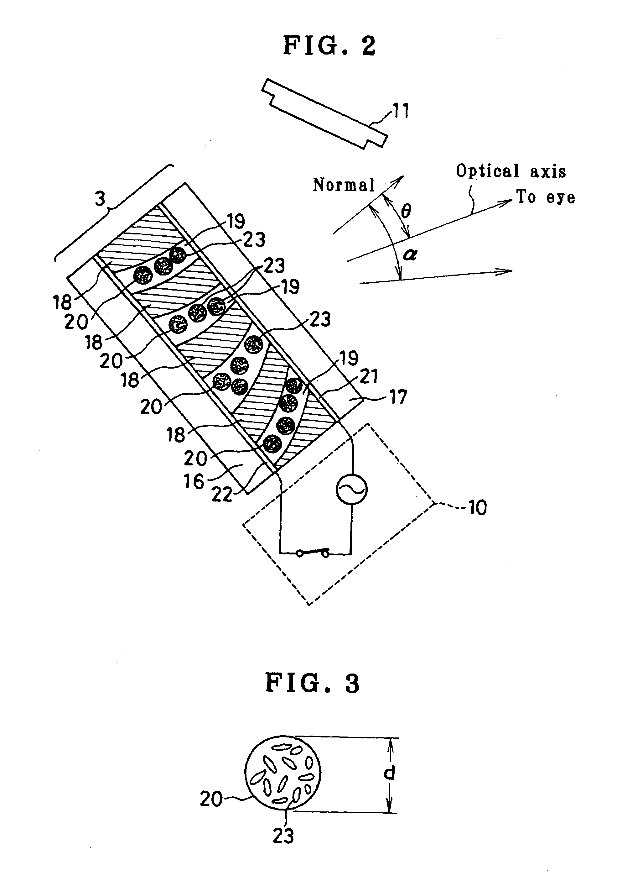
[0067]One embodiment of the variable hologram element according to the present invention, and embodiments of an optical device using the same are now explained.

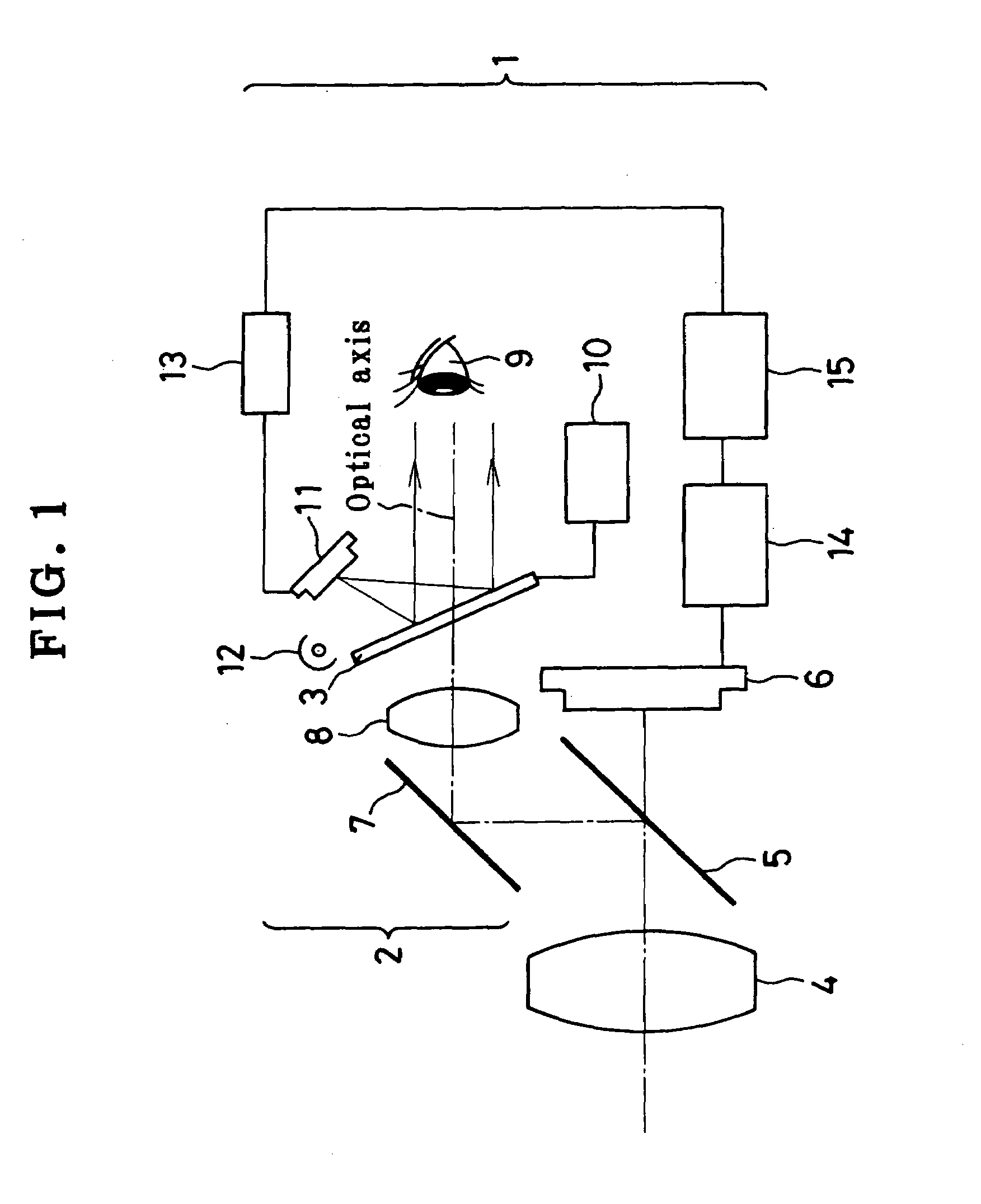
[0068]Illustrated in FIG. 1 is one embodiment of the present invention wherein a liquid crystal variable hologram element (hereinafter LCVHE for short) 3 is used for a finder 2 of an image pickup device 1 such as a digital camera or VTR camera.

[0069]This finder 2 may be used as either an optical finder or an electronic view finder. In FIG. 1 reference numerals 4, 5 and 6 represent an image pickup lens, a half-silvered mirror (or a half-silvered mirror prism) and a solid-state image sensor, respectively.

[0070]Now consider the case where the voltage applied on LCVHE 3 in the image pickup device 1 is held on. A light beam passing through the image pickup lens 4 is partially reflected and bent upwardly at the half-silvered mirror 5, then reflected and bent at the mirror 7 in the right direction, then magnified through a lens 8, a...


PUM

PropertyMeasurementUnit
wavelengthaaaaaaaaaa
refractive indexaaaaaaaaaa
optical propertiesaaaaaaaaaa

Abstract

The invention relates to an optical element with variable optical properties, which ensures that the amount of light available is increased, and an optical device using the same. In a liquid crystal variable hologram element 3, polymer layers 18 and liquid crystal layers 19 are alternately arranged between transparent substrates 16 and 17, with liquid crystal particles 20 lining up in each liquid crystal layer 19. When voltages are applied on transparent electrodes 21 and 22, liquid crystal molecules 23 have their longitudinal directions oriented vertically with respect to the electrodes, so that the refractive index of the polymer layers 18 is substantially equal to that of the liquid crystal layers 19, resulting in no development of hologram. When the voltages are held off, the refractive index of the polymer layers 18 is different from that of the liquid crystal layers 19. This repetition gives rise to an interference fringe action, by which a hologram can be developed. Thus, the variable hologram element 3 can function as a hologram reflecting mirror.

Description

[0001]This is a divisional application of U.S. patent application Ser. No. 09 / 769,750, filed on Jan. 26, 2001, now U.S. Pat No. 6,833,938, and claims benefit of Japanese Patent Application No. 2000-17312 filed in Japan on Jan. 26, 2000, the contents of both of which are incorporated by this reference in their entireties.BACKGROUND OF THE INVENTION[0002]The present invention relates generally to an optical element with variable optical properties and an optical device using the same, and more particularly to a variable hologram element and an optical device using the same.[0003]Among optical elements so far known to have variable optical properties, there is such a liquid crystal lens arrangement 901 as shown in FIG. 23. A light beam incident from the left of the paper is merely converted through a polarizing plate 902 to polarized light, which is then incident on a liquid crystal lens 903. When the voltage applied on the liquid crystal 904 of the liquid crystal lens 903 is held off,...

Claims


Application Information

Patent Timeline
Patent Type & Authority Patents(United States)
IPC IPC(8): G02B5/32G02B27/02G02B23/24G02F1/01G02F1/1334H04N5/225
CPCG02B5/32H04N5/2254G02F2202/32G03H2001/0264H04N2005/2255H04N23/555
Inventor NISHIOKA, KIMIHIKO
Owner OLYMPUS CORP
Why Eureka
Try Eureka