Magnetic head having magnetic pole with lengthened neck pole tip and coplanar yoke, and method of fabrication thereof

a technology of coplanar yoke and magnetic pole, which is applied in the field of magnetic heads, can solve the problems of undesirable elongation of the neck portion of the pole tip, two structures bringing additional challenges, etc., and achieves the effects of promoting better write head switching characteristics, reducing the width of the pole tip at the abs of the magnetic head that is fabricated across the surface of the substrate, and promoting good writing head switching characteristics

Inactive Publication Date: 2006-11-07
HITACHI GLOBAL STORAGE TECH NETHERLANDS BV
View PDF25 Cites 13 Cited by
  • Summary
  • Abstract
  • Description
  • Claims
  • Application Information

AI Technical Summary

Benefits of technology

[0007]The magnetic head of the present invention has a magnetic pole that includes a pole tip portion and a yoke portion. The pole tip is fabricated with an elongated neck portion, having an enlarged anchor piece on one end of the neck and a large yoke interconnection piece on the other end of the neck. The interface between the pole tip and yoke is non-perpendicular to the air bearing surface (ABS) of the magnetic head, and the ABS is located approximately at the midpoint of the elongated neck. As a result, the shadowing effects of the enlarged end pieces during the ion milling notching process do not create significant variations in the width of the neck at locations near the midpoint of the neck. Shadowing effects still exist at locations near the enlarged end pieces, but the shadowing effects are thus away from the central portion of the elongated neck. As a result, variations of the pole tip width at the ABS of the magnetic heads that are fabricated across the surface of the substrate are significantly reduced, and processing yield is therefore increased. The yoke and pole tip neck are both magnetic, however the connection of these two structures brings additional challenges. Ideally, the yoke and pole tip will be formed of dissimilar materials to promote better write head switching characteristics.
[0008]Additionally, for the purposes of rapid magnetic field switching during the magnetic head writing process, it is undesirable to have an elongated neck portion of the pole tip. To resolve this problem, the yoke portion of the second magnetic pole is engaged to the pole tip at a location along the neck that is close to the air bearing surface. In a preferred embodiment, the yoke is fabricated such that the yoke interconnect piece of the pole tip is encapsulated within the yoke. Improved magnetic domain formation in the neck is thereby achieved, such that rapid magnetic field switching of the pole tip can be obtained.
[0009]Because the pole tip and yoke are formed of dissimilar materials, it is particularly desirable to minimize the potential magnetic discontinuity in the normal component of the magnetization in the case where the yoke magnetization direction is parallel to the ABS, which represents either the quiescent state, or that state midway between a reversal during write operation. It is also desirable to do this while keeping the encapsulated portion of the pole tip a small fraction of the total volume of the yoke, thereby minimizing any detrimental effects of the aforementioned undesirable magnetic properties of the high Bs pole tip material. As taught in the present invention, this can be achieved by judicious choice of the geometry of the encapsulated portion of the pole-tip.

Problems solved by technology

The yoke and pole tip neck are both magnetic, however the connection of these two structures brings additional challenges.
Additionally, for the purposes of rapid magnetic field switching during the magnetic head writing process, it is undesirable to have an elongated neck portion of the pole tip.

Method used


Image

  • Magnetic head having magnetic pole with lengthened neck pole tip and coplanar yoke, and method of fabrication thereof
  • Magnetic head having magnetic pole with lengthened neck pole tip and coplanar yoke, and method of fabrication thereof
  • Magnetic head having magnetic pole with lengthened neck pole tip and coplanar yoke, and method of fabrication thereof

Examples


Embodiment Construction

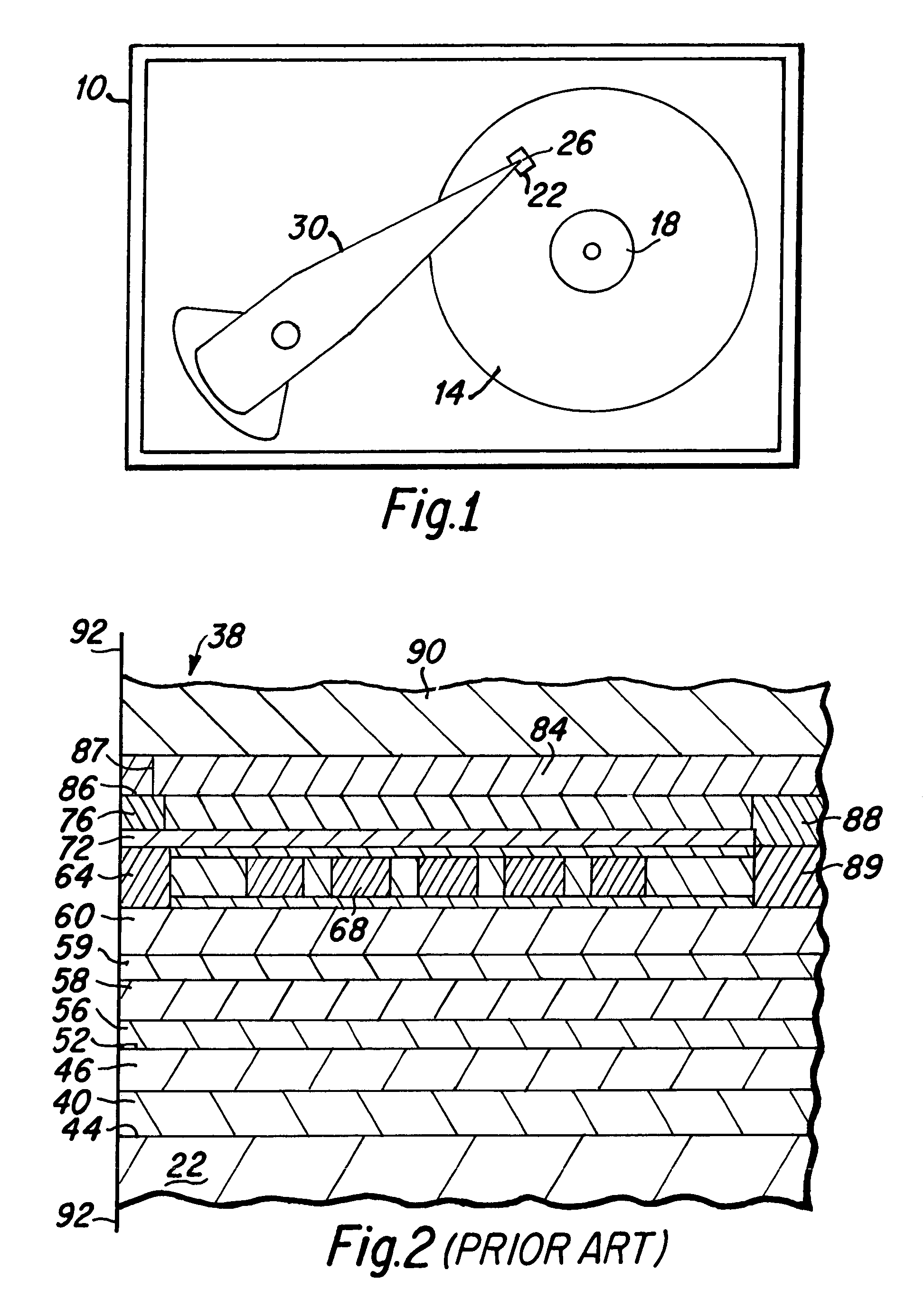
[0033]Efforts to increase areal data storage density of hard disk drives have lead to improvements in the structure and function of the write head elements of magnetic heads. A simplified top plan view of a typical hard disk drive 10 which is suitable to include the magnetic head of the present invention is presented in FIG. 1. As depicted therein, at least one hard disk 14 is rotatably mounted upon a motorized spindle 18. A slider 22, having a magnetic head 26 disposed thereon, is mounted upon an actuator arm 30 to fly above the surface of each rotating hard disk 14, as is well known to those skilled in the art. The present invention includes improved features and manufacturing methods for such magnetic heads 26, and to better described the present invention a prior art magnetic head is next described.

[0034]As will be understood by those skilled in the art, FIG. 2 is a side cross sectional view depicting portions of a prior art magnetic head 38. The magnetic head 38 includes a firs...


PUM

PropertyMeasurementUnit
aspect ratioaaaaaaaaaa
distanceaaaaaaaaaa

Abstract

A magnetic head having a magnetic pole that includes a pole tip and a yoke. The pole tip includes an elongated neck, having an anchor piece on one end and a yoke interconnection piece on the other end. The air bearing surface of the head is located approximately at the midpoint of the elongated neck, and shadowing effects of the end pieces during the ion milling notching process do not create significant variations in the width of the neck at locations near the midpoint of the neck. As a result, variations of the pole tip width at the ABS of fabricated magnetic heads is significantly reduced, and processing yield is therefore increased. The yoke is engaged to the pole tip at a location along the neck that is close to the air bearing surface. In a preferred embodiment, the yoke interconnect piece is encapsulated within the yoke.

Description

BACKGROUND OF THE INVENTION[0001]1. Field of the Invention[0002]The present invention relates generally to magnetic heads that are utilized with thin film hard disk data storage devices, and more particularly to the design and fabrication of a magnetic head having an improved second magnetic pole including a coplanar P2 pole tip and pole yoke.[0003]2. Description of the Prior Art[0004]In the process for fabricating magnetic heads for hard disk drives, thousands of magnetic heads are simultaneously fabricated in rows and columns across the surface of a substrate wafer, and it is a processing consistency goal that each of the magnetic heads be virtually identical. One of the most important magnetic head parameters is the width of the base of the pole tip which determines the track width that data bits will be written by the magnetic head. Therefore, process consistency in identically forming the width of the base of the pole tip of each of the magnetic heads is very important in obtai...

Claims


Application Information

Patent Timeline
Patent Type & Authority Patents(United States)
IPC IPC(8): G11B5/147G11B5/187
CPCG11B5/187
Inventor LILLE, JEFFREY S.SMITH, NEIL
Owner HITACHI GLOBAL STORAGE TECH NETHERLANDS BV
Why Eureka
Try Eureka