Wobble signal reproducing circuit

a technology of wobble signal and reproducing circuit, which is applied in the direction of digital signal error detection/correction, instruments, recording signal processing, etc., can solve the problems of rf signal at the time of passing through the lpp leakage into the wobble signal, and achieve the effect of reducing the offset, improving the accuracy of the circuit, and increasing the mounting area

Inactive Publication Date: 2006-11-07
HITACHI CONSUMER ELECTRONICS CORP
View PDF9 Cites 21 Cited by
  • Summary
  • Abstract
  • Description
  • Claims
  • Application Information

AI Technical Summary

Benefits of technology

[0014]Besides, the wobble signal reproduced in a CD-R / RW has a band width, and the amplitude is varied. In order to reduce an offset due to that at binarization at a later stage, as disclosed in Japanese Patent Unexamined Publication No. Hei 11-161961, it is conceivable that an AGC (AUTOMATIC GAIN CONTROL) circuit is provided at a later stage of the BPF 18. However, in the DVD-RAM, since the groove does not exist in the PID region, it lacks the wobble signal at the time of reproduction of the PID region. Thus, similarly to the above, it is conceivable that this AGC (AUTOMATIC GAIN CONTROL) circuit is saturated in the PID region.
[0015]In the technique disclosed in Japanese Patent Unexamined Publication No. Hei 11-203681, there are a problem of accuracy of wobble signal band detection in the dummy filter and the phase comparison circuit, and a problem that a circuit scale is increased in order to improve the accuracy of the circuit. In the case where band setting of the BPF is made to follow a clock signal reproduced from a wobble signal, it becomes a problem that a ratio of a wobble signal frequency to a clock frequency is different according to the kind of a disk.
[0016]Like this, since the specifications of the wobble signals are different according to the disks, there has been a problem that in the case where the wobble signal reproducing circuits corresponding to the respective disks are provided, a circuit mounting area is increased.

Problems solved by technology

As set forth above, in the case where double speed reproduction of various disks is realized by one optical disk reproducing device, since the specifications of the respective disks are different, various problems occur.
Thus, there is a fear that the RF signal at the time of passing through the LPP leaks into the wobble signal.

Method used


Image

  • Wobble signal reproducing circuit
  • Wobble signal reproducing circuit
  • Wobble signal reproducing circuit

Examples


first embodiment

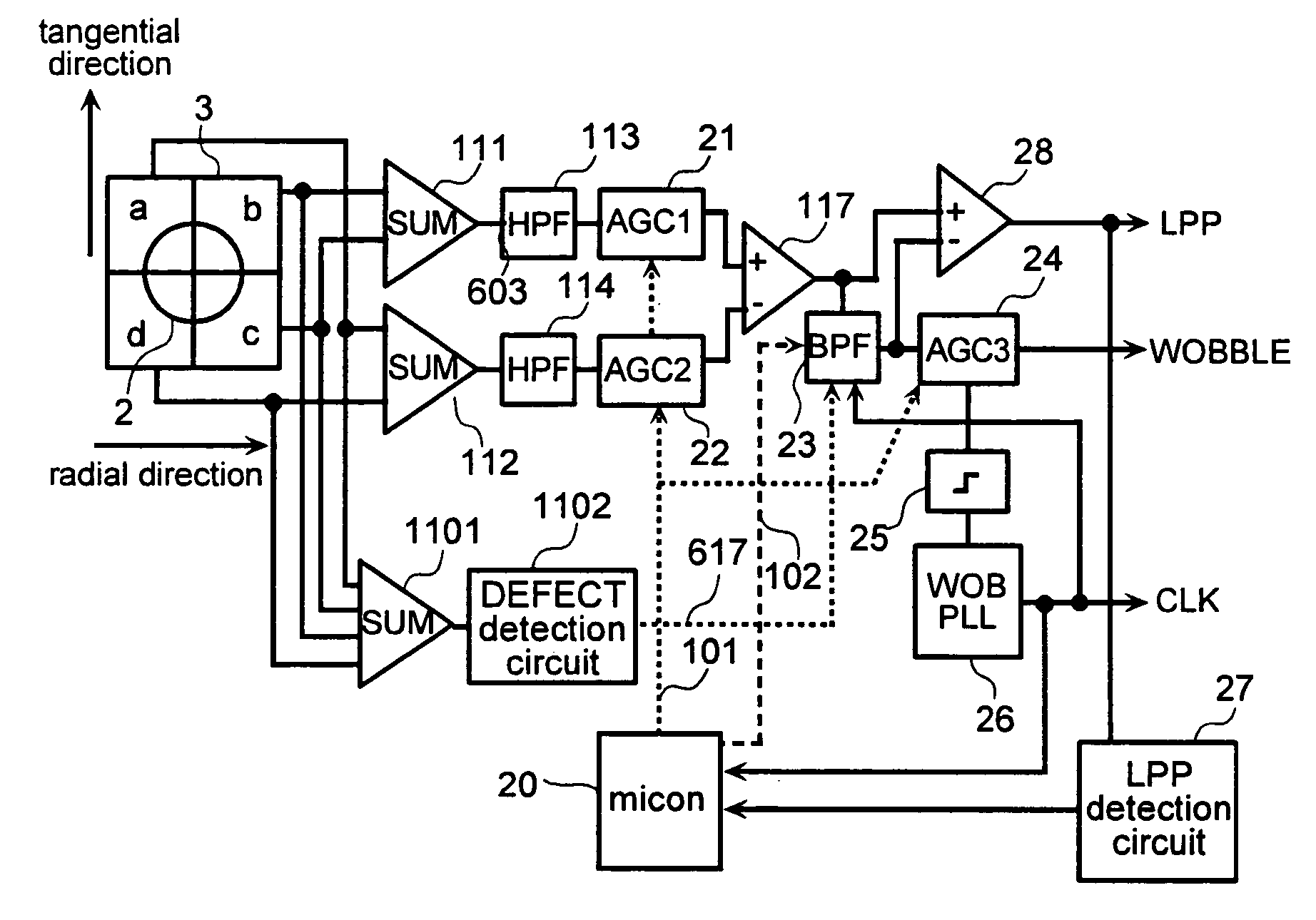
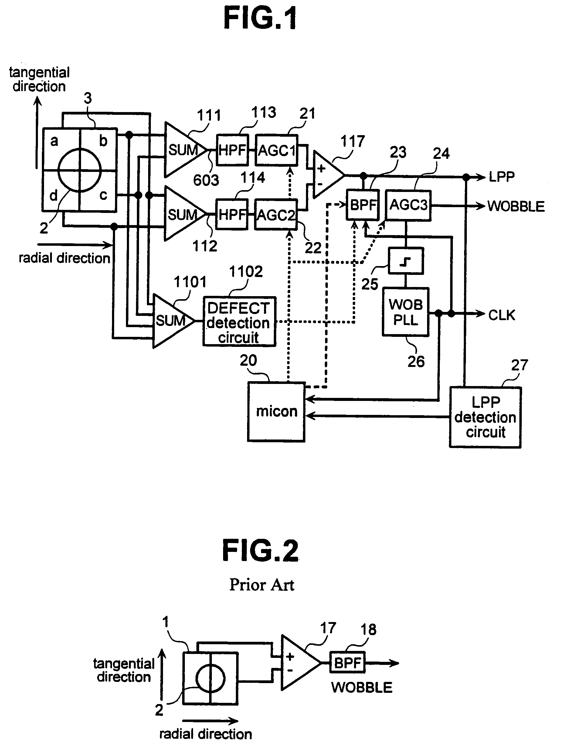
[0042]FIG. 1 is a circuit block diagram of the present invention. In the drawing, a block having the same function as a block in FIG. 2 is designated by the same character as FIG. 2 and its explanation is omitted. Reference numerals 111 and 112 designate wide band adding circuits; 113 and 114, wide band HPFs; and 117, a wide band subtracting circuit. Reference numerals 21, 22 and 24 designate AGC (AUTOMATIC GAIN CONTROL) circuits provided with a gain hold function, and a gain is fixed by a control signal from a microcomputer 20. Among them, the AGC (AUTOMATIC GAIN CONTROL) circuits 21 and 22 disposed at the front stage of a push-pull arithmetic circuit constituted by the subtracting circuit 117 are made wide band AGC (AUTOMATIC GAIN CONTROL) circuits. However, in the case where the HPFs 113 and 114 and the subtracting circuit 117 are defined as the push-pull arithmetic circuit, although the circuits become AGC (AUTOMATIC GAIN CONTROL) circuits disposed in the inside of the push-pull...

second embodiment

[0054]Next, the present invention will be described. FIG. 8 is a block diagram of this embodiment. In the drawing, a block having the same function as a block of FIG. 1 is designated by the same character as FIG. 1 and the explanation is omitted. Reference numeral 28 designates a wide band subtracting circuit, which subtracts an output of a BPF 23 from a wide band push-pull output obtained by a subtracting circuit 117. By this, a wobble frequency component can be removed from the LPP output of FIG. 1, and more stable LPP detection becomes possible.

[0055]FIG. 9 shows an example of a structure of an AGC (AUTOMATIC GAIN CONTROL) circuit in this embodiment. In the drawing, a block having the same function as the AGC (AUTOMATIC GAIN CONTROL) circuit of FIG. 5 is designated by the same character, and the explanation is omitted. Reference numeral 801 designates a capacitor change-over switch, which changes over capacitors 506 and 802 by a control signal 101. Capacitance values C0 and C1 in...

embodiment 1

[0059]At the time of reproduction of a DVD-RAM, since AGC (AUTOMATIC GAIN CONTROL) input becomes signalless in the PID region, the switch 801 is changed over at the time of reproduction of the PID region, and the response time constant of the AGC (AUTOMATIC GAIN CONTROL) circuit is made large. Similarly to the embodiment 1, the detection of the PID region is performed by counting the clock signal reproduced from the wobble signal by the microcomputer. By this, an erroneous operation of the AGC (AUTOMATIC GAIN CONTROL) by input without signal is prevented, and it is possible to stably operate the AGC (AUTOMATIC GAIN CONTROL) even at the time of passing through the PID region.

[0060]From the above, also in this embodiment, similarly to the embodiment 1, the AGC (AUTOMATIC GAIN CONTROL) can be stably operated at the time of recording and reproduction of the CD-R / RW, DVD-R / RW and DVD-RAM, and the same effect as the embodiment 1 can be obtained.

[0061]FIG. 10 shows an example of a structur...


PUM

PropertyMeasurementUnit
frequencyaaaaaaaaaa
pass frequencyaaaaaaaaaa
timeaaaaaaaaaa

Abstract

The present invention has an object to stably reproduce wobble signals of all disks of CD-R/RW, DVD-R/RW and DVD-RAM by one wobble signal reproducing circuit. In the wobble signal reproducing circuit, an AGC (AUTOMATIC GAIN CONTROL) circuit for equating a push-pull circuit output of a wide range and an RF amplitude of an optical detector output of two systems obtained by push-pull, and an AGC (AUTOMATIC GAIN CONTROL) circuit for making a wobble amplitude uniform are provided with a function to hold a gain or to change over a response time constant, and at the time of reproduction of the DVD-R/RW, a land pre-pit region is detected by the push-pull output to hold AGC (AUTOMATIC GAIN CONTROL) or change over a response time constant. Besides, in an address information recording region (PID region) at the time of reproduction of the DVD-RAM, the AGC (AUTOMATIC GAIN CONTROL) is held or the response time constant is changed over.

Description

[0001]This application is a continuation of application Ser. No. 09 / 794,393 filed Feb. 28, 2001 now U.S. Pat. No. 6,785,207.BACKGROUND OF THE INVENTION[0002]1. Field of the Invention[0003]The present invention relates to a reproducing circuit of a wobble signal recorded on a recordable disk of an optical disk.[0004]2. Description of the Related Art[0005]At present, a write once optical disk such as a CD-R / DVD-R, and a recordable optical disk such as a CD-RW / DVD-RW or DVD-RAM, in addition to a read-only optical disk such as a CD or a DVD-RAM, are put on the market. At the time of recording of these recordable optical disks, clock signal generation from a reproduction signal, which is performed in a conventional read-only disk, can not be performed. Thus, a groove as a portion where information is recorded on a disk is wobbled at a constant period, and a clock signal at the time of recording is generated from a wobble signal obtained by reproducing this wobbling (hereinafter referred ...

Claims


Application Information

Patent Timeline
Patent Type & Authority Patents(United States)
IPC IPC(8): G11B20/10G11B19/02G11B7/004G11B7/005G11B7/09
CPCG11B7/005G11B7/0053G11B7/0901G11B7/0941G11B7/0943G11B7/0948G11B2007/0006G11B7/004
Inventor NISHIMURA, KOUICHIROUHIROSE, KOUICHIKATSUKI, MANABUTAKEUCHI, TOSHIFUMI
Owner HITACHI CONSUMER ELECTRONICS CORP
Why Eureka
Try Eureka