System and method for design, procurement and manufacturing collaboration

a technology of procurement and manufacturing collaboration, applied in the direction of instruments, symbolic schematics, cad techniques, etc., can solve the problems of increasing design cost, increasing time to market, and complex cad systems, and achieve the effect of facilitating the performance of manufacturability and facilitating the design of components

Active Publication Date: 2006-11-07
FLEXTRONICS AP LLC
View PDF24 Cites 83 Cited by
  • Summary
  • Abstract
  • Description
  • Claims
  • Application Information

AI Technical Summary

Benefits of technology

[0013]The present invention overcomes the problems associated with the prior art by providing a system and method for integrating an electronic component design tool with business rules filters and design analysis processes. One aspect of the invention facilitates designing components with devices that are pref

Problems solved by technology

While some CAD systems appear quite complex, and offer the designer a great variety of drawing tools, such programs are essentially only drawing engines.
In summary, the multiple redesigns in t

Method used


Image

  • System and method for design, procurement and manufacturing collaboration
  • System and method for design, procurement and manufacturing collaboration
  • System and method for design, procurement and manufacturing collaboration

Examples


Embodiment Construction

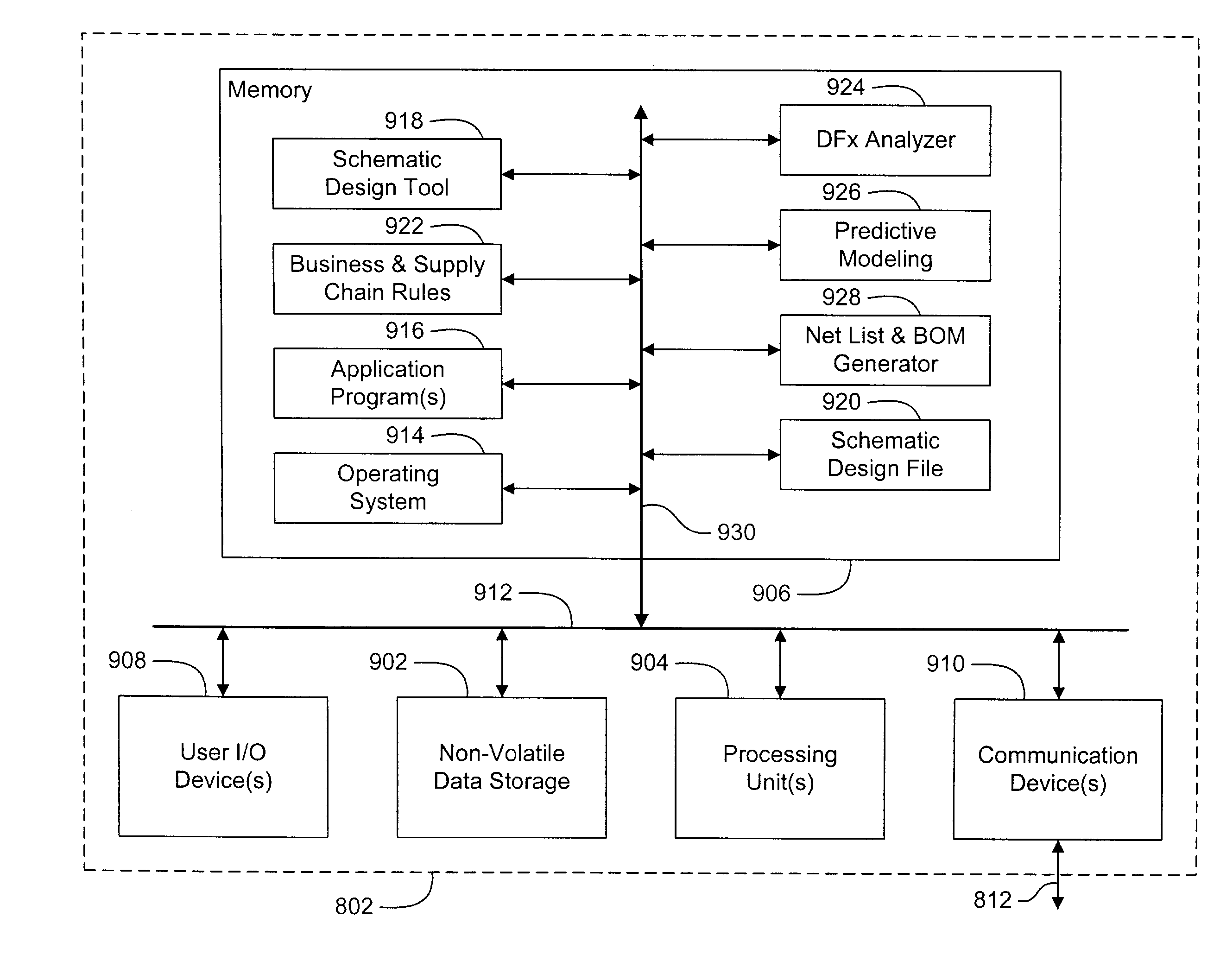
[0038]The present invention overcomes the problems associated with the prior art, by integrating supply chain information and / or DFx analysis with a schematic design tool. In the following description, numerous specific details are set forth (e.g., particular data structures, particular types of DFx analysis, etc.) in order to provide a thorough understanding of the invention. Those skilled in the art will recognize, however, that the invention may be practiced apart from these specific details. In other instances, details of well-known computer programming practices (e.g., provision of APIs, database management, etc.) have been omitted, so as not to unnecessarily obscure the present invention.

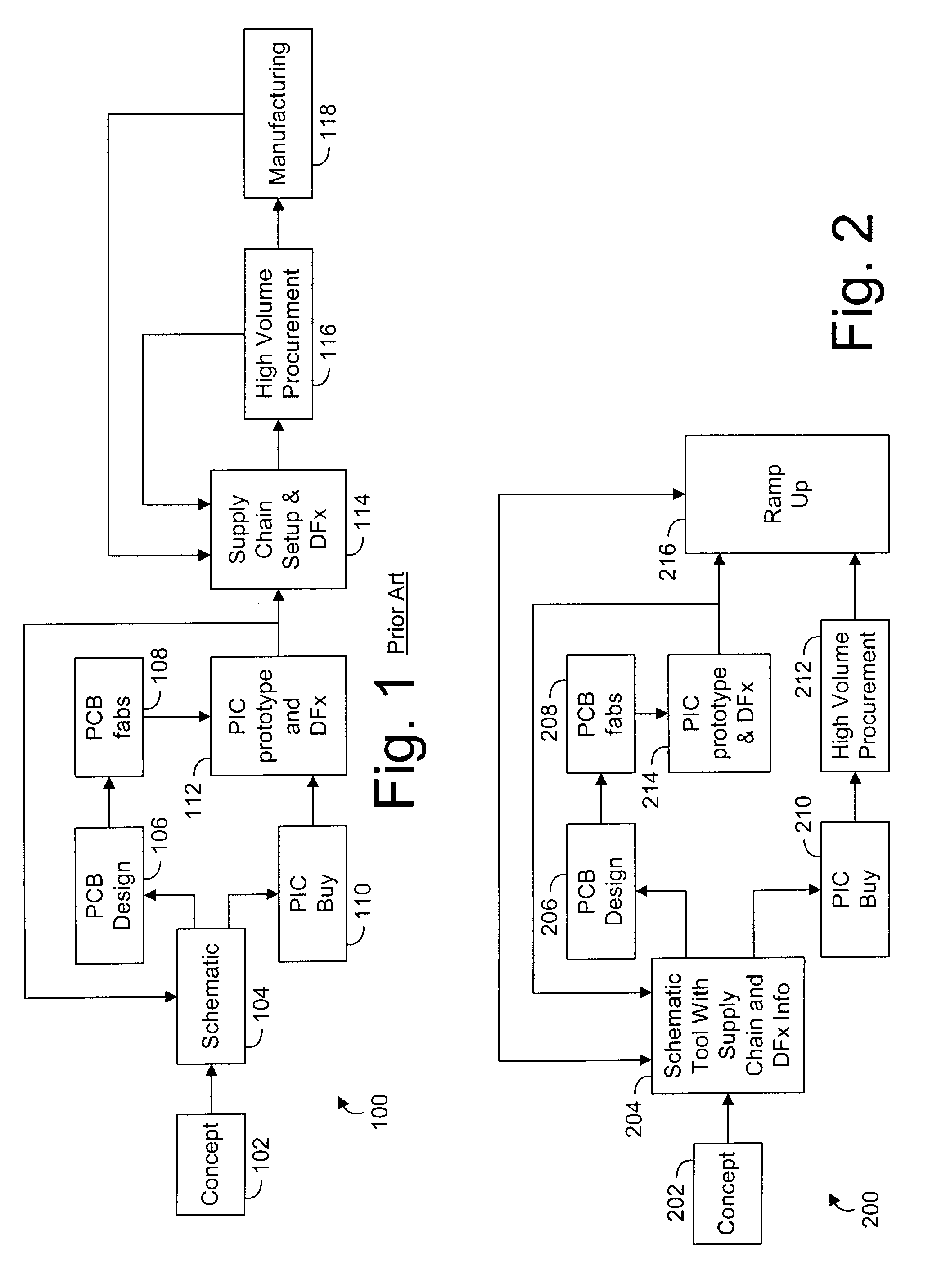
[0039]FIG. 2 illustrates a process 200 of taking an electronic component from conception to manufacture according to one aspect of the present invention. The first conception stage 202 is not unlike the conception stage 102 in the process of the prior art. In the design stage 204, however, the...


PUM


Abstract

A method for designing an electronic component includes receiving a device criteria (e.g., a parametric value, procurement value, etc.) from a designer, querying a database for devices corresponding to the device criteria, querying the database for procurement data and/or engineering data associated with the corresponding devices, presenting the devices to the designer based on the procurement data, and receiving input from the designer identifying one of the presented devices as a selected device. In a particular method, the returned devices are sorted based on one or more procurement values (e.g., manufacturer, price, availability, manufacturer status, etc.), and presented to the designer in a ranked list. Objects representative of the selected devices are then entered into a design file, and the objects are associated with the device's engineering and/or procurement data. In a particular embodiment, the objects are associated with the engineering data by embedding the engineering data in the file object. Optionally, data can be associated with the objects via links to the database. Types of engineering data that can be associated with design file objects include, but are not limited to, device footprint data, device pinout data, device physical dimension data, parametric data, and packaging data. Additionally, connection data and annotation data can be entered into the design file objects by the designer.

Description

RELATED APPLICATIONS[0001]This application claims priority to U.S. Provisional Patent Application Ser. No. 60 / 359,424, filed on Feb. 22, 2002 by at least one common inventor, and which is incorporated herein by reference in its entirety.BACKGROUND OF THE INVENTION[0002]1. Field of the Invention[0003]This invention relates generally to the design and manufacture of electronic components, and more particularly to a schematic design tool capable of integrating design and procurement analysis at the design stage of a component.[0004]2. Description of the Background Art[0005]Computer Aided Design (CAD) systems are well known and widely used in the design of electronic circuits. Known systems allow the designer to enter objects into an electronic drawing file and to connect the objects in order to “draw” the circuit being designed.[0006]While some CAD systems appear quite complex, and offer the designer a great variety of drawing tools, such programs are essentially only drawing engines. ...

Claims


Application Information

Patent Timeline
IPC IPC(8): G06F17/50G06F19/00G06Q50/00
CPCG06F17/50G06Q99/00G06Q90/00G06F17/5081G06F17/5045G06F2217/04G06F2217/74G06F2217/00G06F2111/02G06F30/00G06F30/30G06F2111/12G06F30/398G06F2111/00G06F2119/18
Inventor BRATHWAITE, NICHOLAS E.BOMMAKANTI, RAM GOPALGANAPATHY, VISVANATHANBURNS, PAUL N.MADDOX, DOUGLAS EDWARDDURKAN, MICHAEL ANTHONY
Owner FLEXTRONICS AP LLC
Why Eureka
Try Eureka