Method and apparatus for efficient register-transfer level (RTL) power estimation

a technology of register transfer level and power estimation, applied in the direction of cad circuit design, program control, instruments, etc., can solve the problems of inability to address all the challenges, inability to complete the training sequence used to construct the macro-model, and inability to meet the requirements of efficiency considerations, etc., to achieve enhanced rtl description of the circuit, accelerated power estimation, and more friendly to simulators

Inactive Publication Date: 2006-11-07
NEC CORP
View PDF4 Cites 60 Cited by
  • Summary
  • Abstract
  • Description
  • Claims
  • Application Information

AI Technical Summary

Benefits of technology

[0086]To realize the advantages discussed above, the disclosed teachings provide a method for accelerating power estimation for a circuit comprising generating an RTL description of the circuit. A power model enhanced RTL description of the circuit is generated. A simulator is selected. The power model enhanced RTL description is modified to make it more friendly to the simulator. The simulator is run to estimate the power consumed by the circuit.

Problems solved by technology

The resulting opportunities to deploy RTL estimation technologies (that have been extensively researched but limited in their commercial use) are accompanied by many significant challenges.
While such techniques are error-prone in general, they may be accurate for some parts of a chip for which the complexity parameters are easy to estimate (e.g., memories and clock networks ).
However, there are several challenges that need to be addressed.
The training sequences used to construct the macro-model cannot be exhaustive due to efficiency considerations.
Since characterization is done up front with possibly little information about the environment in which the components are going to be used, the training sequences may not very well represent real-life input sequences.
In addition to the above problem, macro-models may introduce inaccuracies since the results of the characterization experiments are fit into a predetermined function template or model, resulting in some errors due to interpolation or extrapolation (fitting error).
This reduces the re-characterization effort involved in “porting” the macro-models to reflect a new technology or synthesis flow.
It is also important to take into account the glitching activity at the control signals since it can have a significant impact on the power consumption in the rest of the design .
Power aggregation code, which accumulates the power consumption of the RTL components in the design.
This summation process is performed in a hierarchical manner, corresponding to the hierarchy of the design itself, resulting in power consumption estimates for any instance in the design hierarchy in addition to the entire design.
As described in Section IV, judicious control of the signals that activate power estimation code can result in significant speedups in power estimation with minimal loss of accuracy.

Method used


Image

  • Method and apparatus for efficient register-transfer level (RTL) power estimation
  • Method and apparatus for efficient register-transfer level (RTL) power estimation
  • Method and apparatus for efficient register-transfer level (RTL) power estimation

Examples


example 1

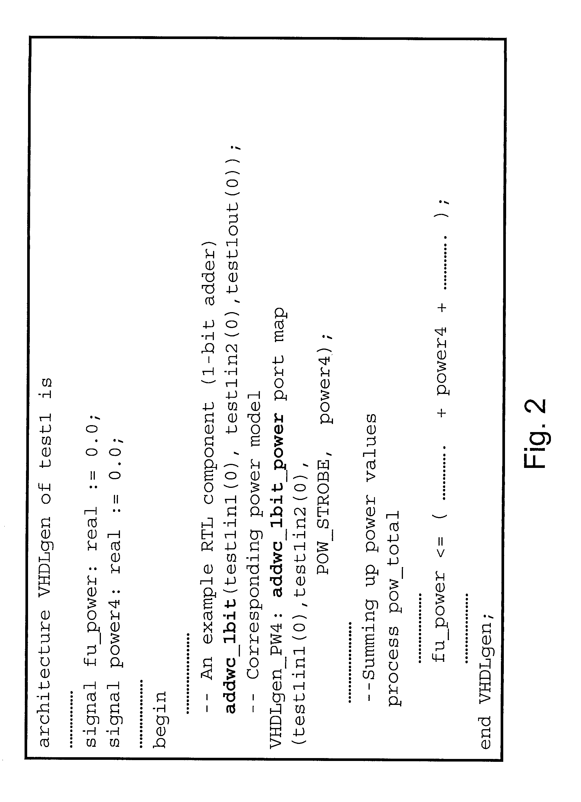
[0136]FIG. 2 gives the HDL description of a design test1, which has an RTL component addwc—1bit and the corresponding power model addwc—1bit_power instantiated in it. Module addwc—1bit has two inputs, test1in1(0) and test1in2(0), and one output, test1out(0). Both test1in1(0) and test1in2(0) form the inputs to the power model addwc—1bit_power. The other input to the power model is its activation signal POW_STROBE and the computed power consumption value power4.

[0137]The HDL code generated for the power model is shown in FIG. 3. The HDL description shows a single process which is sensitive to any event on the POW_STROBE signal. The first action of the process is to update the status of the queues that store the previous and current values of the inputs / outputs of addwc—1bit. This is followed by the actual evaluation of power consumption as a function of the bit-level transitions using the function trans_count. FIG. 4 gives an example specification of the function trans_count that simp...

example 2

[0146]Consider the basic power model addwc—1bit_power seen earlier in FIG. 3 When a falling edge event is seen on POW_STROBE, q_in1 and q_in2 first update the contents of the previous and current values. Then, the power consumption is computed as a function of q_in1 and q_in2.

[0147]Delayed computation can be applied to this power model and the modified VHDL specification for addwc—1bit_power is given in FIG. 7. Here, the store and compute operations of the power model are separated into two phases activated by separate strobing signals. The signal STORE_STROBE is applied every cycle to update the queues q_in1 and q_in2 (now of length k). The signal POW_STROBE is applied only in the kth cycle to evaluate power consumption. Note that function trans_count changes to accomodate k-long queues (see FIG. 8).

[0148]Note that the amount of additional storage required by the simulator to store component values is directly proportional to the size of the design and k. FIG. 9 shows the variation...

example 3

[0178]FIG. 13 lists the aggregate mean power (Σcomp∈ci{overscore (P)}comp), aggregate standard deviation (Σcomp∈ciScomp) and the number of RTL components (|Ci|) for the clusters C1, C2 and C3 shown in FIG. 12(b).

[0179]From this data, the objective function that is to be minimized is formulated (see Equations 4 and 6)

ΔP=constant*(0.59 / sqrt(N1)+51.5 / sqrt(N2)+2.24 / sqrt(N3))  (9)

[0180]If Ntot is 300,000 and nf is 10%, the allowed budget of samples is 30,000. Then, it follows from Equation 7 that the constraints for minimizing Equation 9 are

120.N1+256.N2+85.N3Ni>=1∀i=1  (10)

[0181]Minimizing Equation 9 subject to the constraints in Equation 10 yields N1=9, N2=104 and N3=27. Therefore, the desired sampling probabilities Pr1, Pr2 and Pr3 are 0.04, 0.89 and 0.11, respectively.

[0182]IV.C Systems for Power Estimation

[0183]The above discussed techniques are used to build systems for estimating power in electronic circuits described at the register-transfer level (RTL). A power estimation system...


PUM


Abstract

Techniques for accelerating power estimation for a circuit comprising generating an RTL description of the circuit. A power model enhanced RTL description of the circuit is generated. A simulator is selected. The power model enhanced RTL description is modified to make it more friendly to the simulator. The simulator is run to estimate the power consumed by the circuit. Techniques using delayed computation and partitioned sampling are also provided. Power estimation systems using the above techniques area also provided.

Description

I. DESCRIPTION[0001]I.A. Field[0002]This disclosure teaches power estimation methods and apparatus in relation to commercial design flow for power estimation of RTL circuits. Specifically, enhancements that improve the efficiency and scalability of power estimation tools for large RTL circuit designs are disclosed.[0003]I.B. Background1. REFERENCES [0004]The following papers provide useful background information, for which they are incorporated herein by reference in their entirety, and are selectively referred to in the remainder of this disclosure by their accompanying reference numbers in triangular brackets (i.e., <3> for the third numbered paper by E. Macii et al.):[0005]<1> P. Landman, “High-level power estimation,” in Proc. Int. Symp. Low Power Electronics & Design, pp. 29–35, August 1996.[0006]<2> A. Raghunathan, N. K. Jha, and S. Dey, High-level Power Analysis and Optimization. Kluwer Academic Publishers, Norwell, Mass., 1998.[0007]<3> E. Macii, M. P...

Claims


Application Information

Patent Timeline
Patent Type & Authority Patents(United States)
IPC IPC(8): G06F17/50
CPCG06F17/5022G06F2217/78G06F30/33G06F2119/06
Inventor RAVI, SRIVATHSRAGHUNATHAN, ANANDCHAKRADHAR, SRIMAT T.
Owner NEC CORP
Why Eureka
Try Eureka