System for integrating mid-range and high-frequency acoustic sources in multi-way loudspeakers

Inactive Publication Date: 2006-11-14
HARMAN INT IND INC
View PDF32 Cites 26 Cited by
  • Summary
  • Abstract
  • Description
  • Claims
  • Application Information

AI Technical Summary

Benefits of technology

[0012]Besides integrating the mid-range and high-frequency sound waves, the RBI may be used to compression load the mid-range frequency sound waves to improve the acoustic power output of the mid-range sound sources. Compression loading is accomplished by contouring the surface of the RBI that faces the mid-range sound sources, i.e., the back surface of the RBI, to the shape of the mid-range sound sources or speakers. Contouring the back surface reduces the space between the back surface of the RBI and the sound sources. The reduced space compression loads the mid-range freque

Problems solved by technology

This severely limits the predictability and control of the direction of the sound radiation.
One of the problems with the design of certain loudspeaker systems is that the cones of the midrange sound sources form a recess or depression in the adjacent sidewalls.
The angular radiation of high frequencies conforms to the cont

Method used


Image

  • System for integrating mid-range and high-frequency acoustic sources in multi-way loudspeakers
  • System for integrating mid-range and high-frequency acoustic sources in multi-way loudspeakers
  • System for integrating mid-range and high-frequency acoustic sources in multi-way loudspeakers

Examples


Embodiment Construction

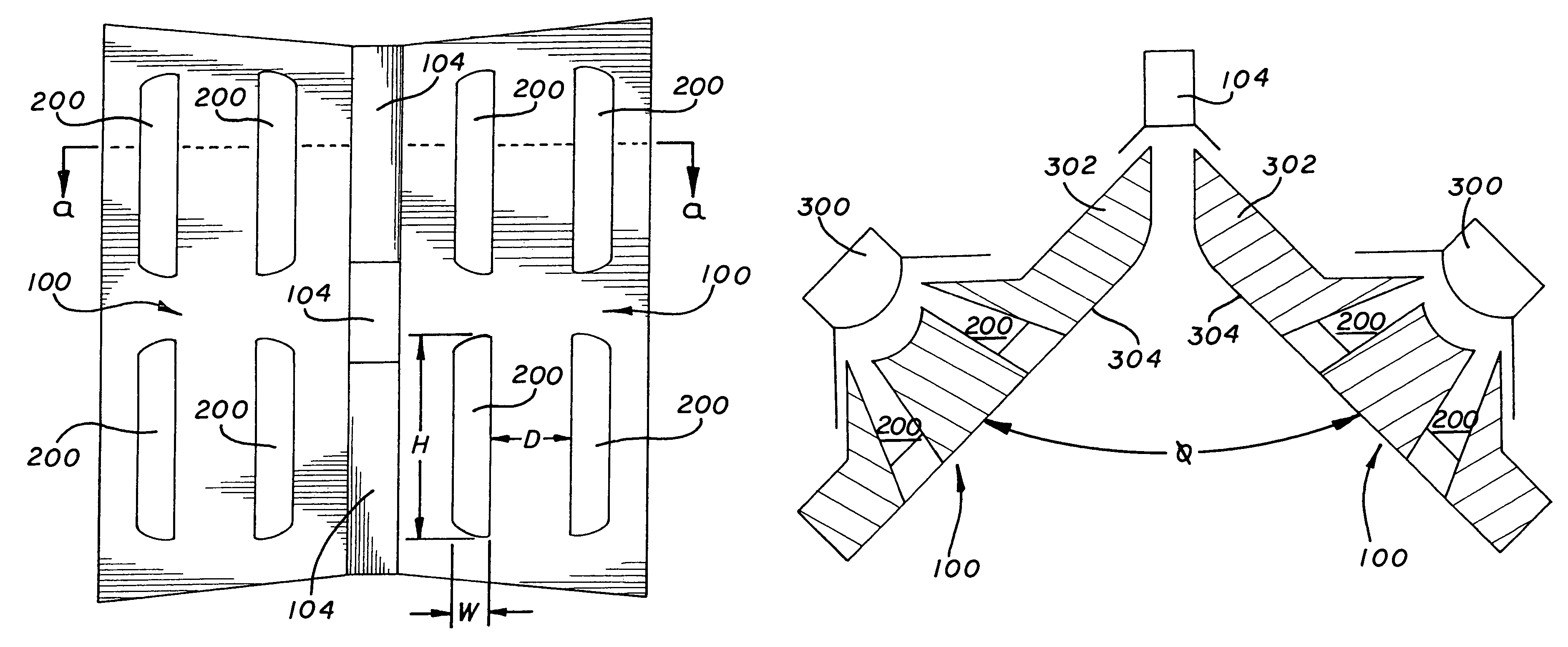
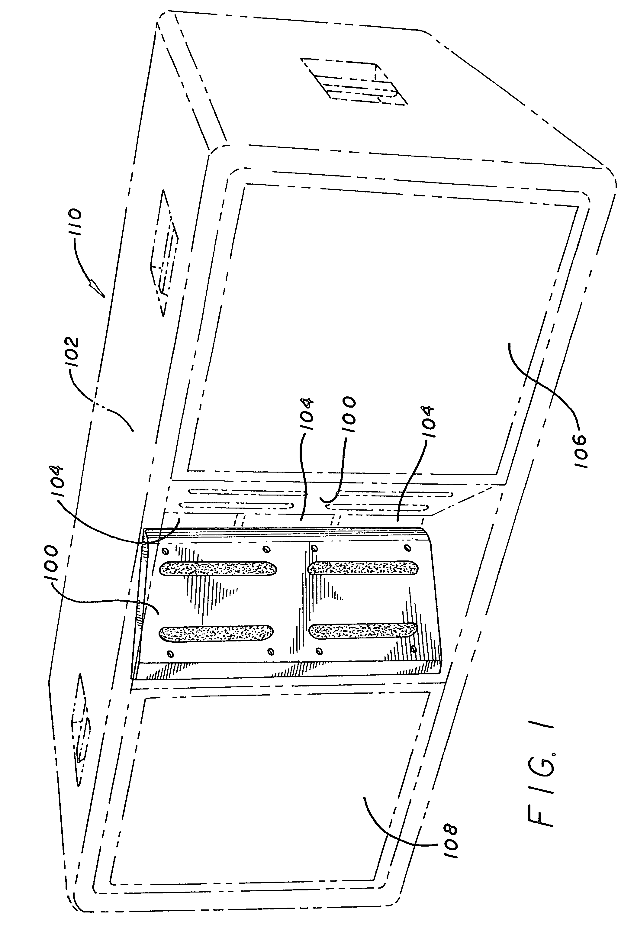
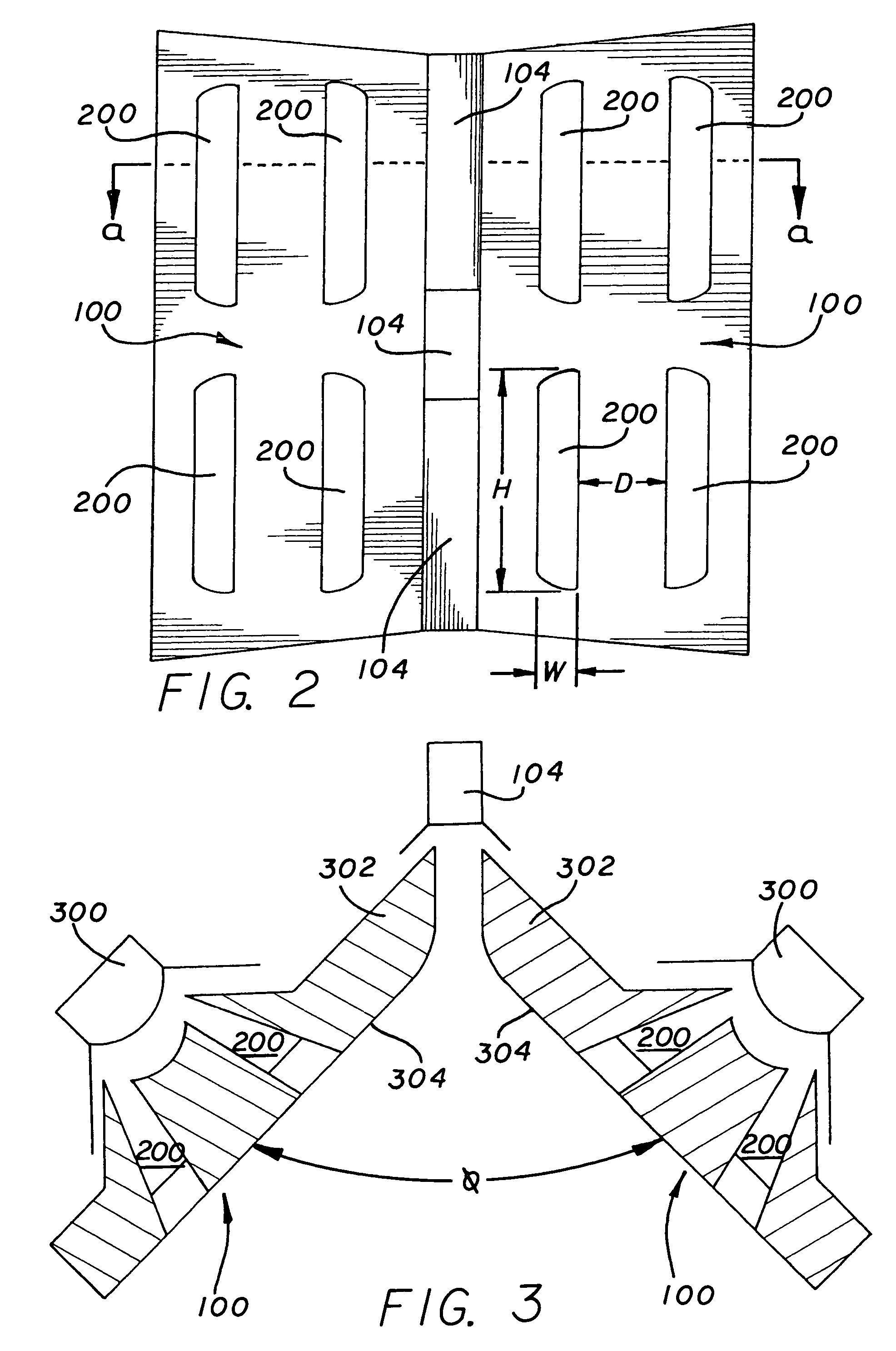
[0028]FIG. 1 is a perspective view of a multi-way loudspeaker 110 use two sound integrators or radiation boundary integrators (“RBIs”) 100. FIG. 1 illustrates the two RBIs 100 as they would appear positioned within a multi-way loudspeaker housing 102 (“housing”). In the exemplary line array speaker 110, a plurality of high-frequency sound sources 104 are stacked vertically in the mid-section of the housing 102. Two adjacent side walls (not shown) extend outwardly from the high-frequency sound sources 104 forming an angle relative to each other such that the high-frequency sound sources 104 are at the vertex of the two adjacent side walls. Flush within each of the side wall is at least one mid-range sound source (see FIG. 3). Each side wall is covered with the RBI 100 so that the high-frequency sound sources 104 are at the vertex of the two RBIs100. Besides the high frequency 104 and mid-range frequency sound sources, the housing 102 may also incorporate low-frequency sound sources 1...


PUM


Abstract

This invention provides a radiation boundary integrator (“RBI”) for integrating sound radiation from mid-range and high-frequency sources in multi-way loudspeakers. The RBI is a substantially solid boundary that is placed over the mid-range speakers to provide smooth, wave-guiding side walls to control the angular radiation of the high-frequency sound waves emanating from the high-frequency sound sources. To allow the mid-range frequency sound waves generated from mid-range sound sources to pass through the RBI, the RBI is designed with openings. To further prevent the possibility of having high-frequency sound radiate through the openings in the RBI, the RBI may be designed with porous material in the openings of the RBI. The porous material would be transparent to the mid-range sound radiation, but would prevent the high-frequency sound radiation from being disturbed by the openings in the RBI. As such, the RBI provides an outer or front surface area that forms an acoustical barrier to high frequencies radiating across the front surface, yet is acoustically transparent to mid-range frequencies radiating through openings in the RBI. The RBI may also serve as a volume displacement device to compression-load the mid-range sound sources by contouring the back side of the RBI to the shape of the mid-range sound sources thus reducing the space between the RBI and the mid-range sound sources and loading the mid-range sound sources to generate greater mid-range sound energy.

Description

CROSS-REFERENCE TO RELATED APPLICATIONS[0001]This application is a continuation of U.S. patent application Ser. No. 09 / 921,175, filed Jul. 31, 2001, now abandoned which claims priority to U.S. Provisional Patent Application Ser. No. 60 / 222,026, filed Jul. 31, 2000. Both U.S. patent application Ser. No. 09 / 921,175 and No. 60 / 222,026 are incorporated by reference.BACKGROUND OF THE INVENTION[0002]1. Field of the Invention[0003]This invention relates generally to a system for integrating the sound radiating from multi-way loudspeakers. In particular, the invention relates to a radiation boundary integrator positioned over a mid-range sound source to prevent angular radiation from high frequencies from conforming to the contours of the cones or diaphragms of the mid-range frequency sound source.[0004]2. Related Art[0005]Loudspeakers and sound systems are designed to control the direction of the sound radiating from their sound sources. Sound radiating from a high-frequency sound source, ...

Claims


Application Information

Patent Timeline
IPC IPC(8): H05K5/04G10K11/02G10K11/04H04R1/20H04R1/24A47B81/06H04R1/02H05K5/00H04R1/28H04R1/32H04R1/40
CPCH04R1/26H04R1/288H04R1/30H04R1/323H04R1/403
Inventor ENGEBRETSON, MARK
Owner HARMAN INT IND INC
Why Eureka
Try Eureka