
Soil moisture sensor

Inactive Publication Date: 2006-11-14
UNITED STATES OF AMERICA AS REPRESENTED BY THE SEC OF AGRI THE
View PDF2 Cites 39 Cited by
  • Summary
  • Abstract
  • Description
  • Claims
  • Application Information

AI Technical Summary

Benefits of technology

[0023]Another object of this invention is to provide a microwave process and system for measuring the moisture content of soil wherein the frequency can be adjusted and controlled for a more accurate and stable measurement.
[0024]Yet another object of this invention to provide a narrow band frequency technique that provides a low cost accurate method for the determination of the soil's dielectric constant, complex permittivity, and moisture content.

Problems solved by technology

Thus, the TDR technique while accurate, requires very expensive circuitry in order to accurately measure the delay (GHz or faster clock).
This has lead to the TDR technique being predominantly used by only the research community at the cost of neglecting the bulk of the irrigation market that is comprised of growers, and landscapers.
Another disadvantage to the TDR method is due to the very broad frequency band-width the system requires due to the technique's use of a very rapid rise-time ns-duration pulse.
This disadvantage is best illustrated by noting that the frequency spectrum of a pulse is extremely wide and when taken to the extreme with an infinitely narrow pulse-width, leads to an infinitely wide frequency spectrum.
Thus, this technique is, by it's design, an extremely broad-band technique that cannot take advantage of the frequency-based variability that naturally occurs in the dielectric spectrum.
Unfortunately, however resonant structures typically are extremely temperature sensitive and as such have had very limited success in the industry as well as the research community due to the difficulties in calibrating these types of instruments across the temperature range of interest and use.
The main trouble with these types of instruments lies in their inability to work at microwave frequencies which is where the effect of salinity no longer affects the measurement.
Thus, these lower frequency systems are subjected to a dependence upon the soil's salinity as a confounding element affecting the reading.
As such, all of these patents provide very expensive solutions.

Method used


Image

  • Soil moisture sensor
  • Soil moisture sensor
  • Soil moisture sensor

Examples


example 1

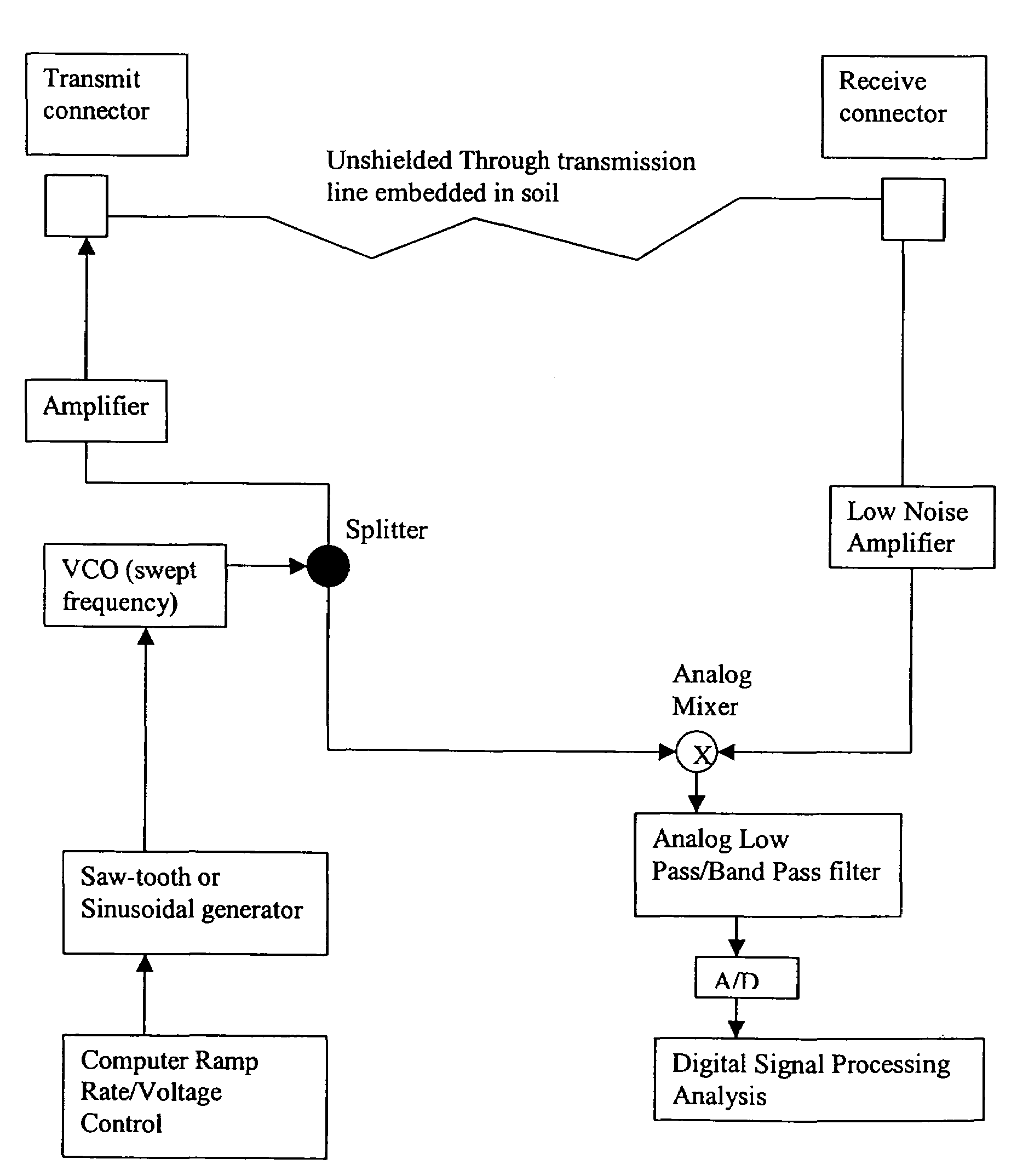
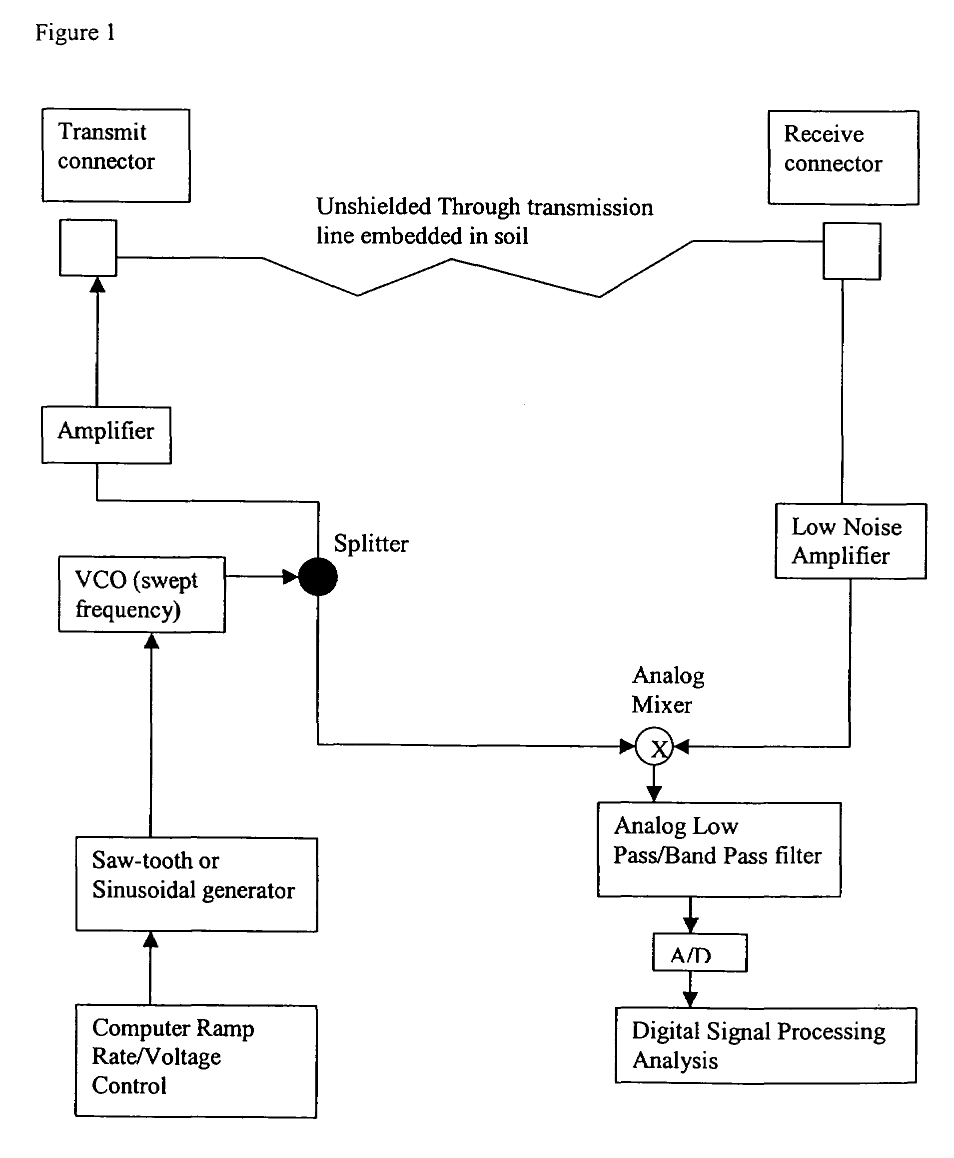
[0074]A preferred apparatus was constructed for measuring the moisture of soil which is shown in FIG. 1 and described above.

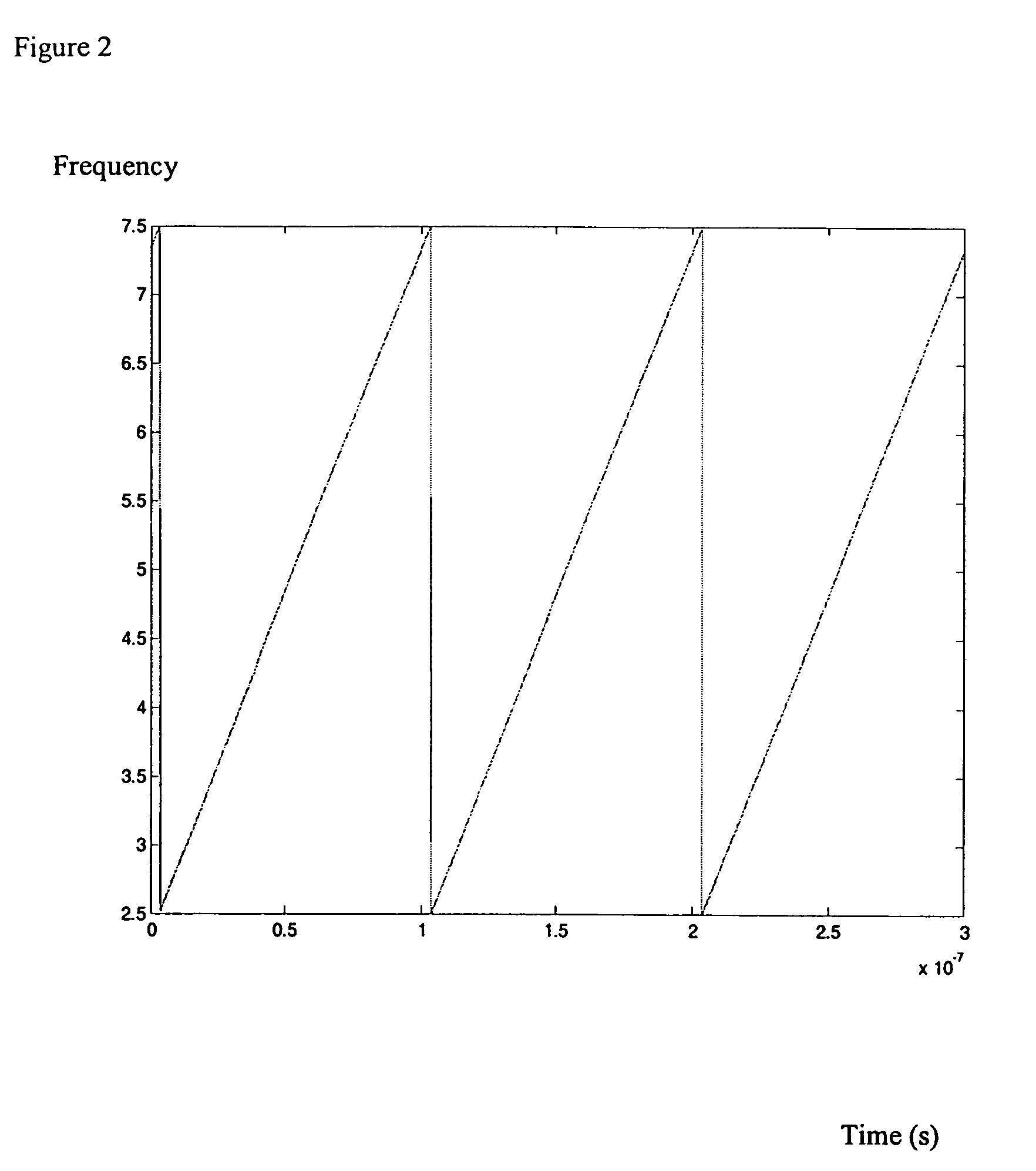
[0075]Step 1: Generate a control voltage in the form of a Saw Tooth or Sinusoidal waveform whose voltage range is such that the preferred maximum frequency deviation of the voltage controlled oscillator (VCO) is less than 100 MHz in order to achieve an accurate measure of moisture. The frequency repetition rate should be at least 1 kHz when utilizing a 100 MHz frequency deviation. In the generation of this control voltage signal it is imperative that either a continuously varying analog signal is utilized or in the case of digital synthesis techniques that the rate of change between the discrete voltage steps are rapid enough to ensure that the received signal 1 is at a different frequency than the internal reference signal 2 when both arrive at the mixer of steps 5 and 8. It should be noted that in the discrete generation version of producing the control volta...


PUM


Abstract

The moisture content of soil may be determined using a swept-frequency microwave-based process and device. The process includes the steps of: producing a primary microwave signal with a varying frequency, splitting the primary signal to provide first and second microwave signals, which first signal is transmitted through an electric conductor in the soil where it will be delayed in proportion to the dielectric constant of the soil, while the second signal provides an internal reference signal, receiving a third signal which includes the first signal after it has passed through the electrical conductor, mixing the third signal together with the second signal, generating a mixed signal, filtering the mixed signal to remove upper side-band interference signals, generating a filtered-mixed signal, measuring the frequency of the filtered-mixed signal and calculating the moisture content of the soil.

Description

[0001]This application hereby claims the benefit of U.S. provisional patent application 60 / 640,343, filed Dec. 30, 2004, the content of which are incorporated by reference herein.BACKGROUND OF THE INVENTION[0002]1. Field of the Invention[0003]The invention relates to an improved microwave system for measuring the moisture content of soil.[0004]2. Description of the Prior Art[0005]Evaluation of soil water content is a fundamental operation for irrigation scheduling in crop production, management and research. To date, the most effective method of measuring the soil water in the root zone is by the TDR technique. Numerous researchers over the last 20 years have shown the TDR technique provides a reliable measure of soil moisture through the estimation of the soil's dielectric constant, Heathman G. C.*, Starks P. J and Brown M. A. 2003. Other inventions based upon the TDR technique include U.S. Pat. Nos. 6,657,443, 5,726,578, 4,918,375.[0006]In traditional TDR measurements, a rapid ris...

Claims


Application Information

Patent Timeline
IPC IPC(8): G01R27/04
CPCG01N22/04G01N33/246
Inventor PELLETIER, MATHEW G.
Owner UNITED STATES OF AMERICA AS REPRESENTED BY THE SEC OF AGRI THE
Learn More