Adjusting device for a thermal trip

a technology of adjustment device and thermal release, which is applied in the direction of relays, circuit-breaking switches, protective switch details, etc., can solve the problems of corresponding production and manufacturing costs of adjusting screws, and achieve the effect of cost-reducing production and simple and low-cost adjustmen

Inactive Publication Date: 2006-11-14
SIEMENS AG
View PDF27 Cites 23 Cited by
  • Summary
  • Abstract
  • Description
  • Claims
  • Application Information

AI Technical Summary

Benefits of technology

[0009]An embodiment of the invention includes an object of specifying a particularly cost-effective adjustment apparatus, which can be adjusted easily, for a switching device, in particular for a line circuit breaker.
[0010]The bimetallic strip mount has a holding limb, which runs parallel to the bimetallic strip, is connected to its contact end and has a fixing end as a fixed attachment point. This holding limb, which is preferably curved in the form of a step, is adjacent on one side to a handling limb, which acts as an adjustment area, and on the other side via a bend to an at least approximately U-shaped fixing limb of the bimetallic strip mount. The stepped contour of the holding limb makes it possible to hold bimetallic strips of different length, in particular also including bimetallic strips which can be heated indirectly, by means of the same bimetallic strip mount. This makes it possible to considerably reduce the number of different thermal releases which have to be provided or kept available for different types of switching device and, in particular, to keep this number small overall.
[0013]The switching device has a housing which is formed from urea and / or melamine resin molding compound. The urea or melamine resins, which are included in the family of thermosetting plastics, are particularly suitable for cost-reducing production of mass-produced items and batch-produced items.
[0014]The advantages that are achieved by an embodiment of the invention are, in particular, that suitable refinement and arrangement of a bimetallic strip mount to which the bimetallic strip is fitted allows the bimetallic strip mount to be deformed deliberately, thus making it possible to provide a simple and low-cost adjustment apparatus, which if required is self-adjusting, for a thermal release for a switching device. The distance between the free end of the bimetallic strip and the tripping lever can in this case be set or adjusted on the one hand by deformation, in particular by twisting, if necessary by way of a tool for the handling and holding limb, and on the other hand makes it possible to compensate for ageing-dependent housing shrinkage resulting from autonomous bending of the bimetallic strip mount.
[0015]This mechanism, which is used to adjust the bimetallic strip, and in which the bimetallic strip mount that holds the bimetallic strip is mounted fixed to the housing via two attachment points, one fixed attachment point of which ensures robust mounting of the bimetallic strip—and thus of the thermal release—while the other attachment point includes the adjusting device for adjustment of the bimetallic strip by deformation, allows fine and exact adjustment of the thermal release.

Problems solved by technology

However, the use of an adjusting screw is associated with corresponding production and manufacturing costs.

Method used


Image

  • Adjusting device for a thermal trip
  • Adjusting device for a thermal trip
  • Adjusting device for a thermal trip

Examples


Embodiment Construction

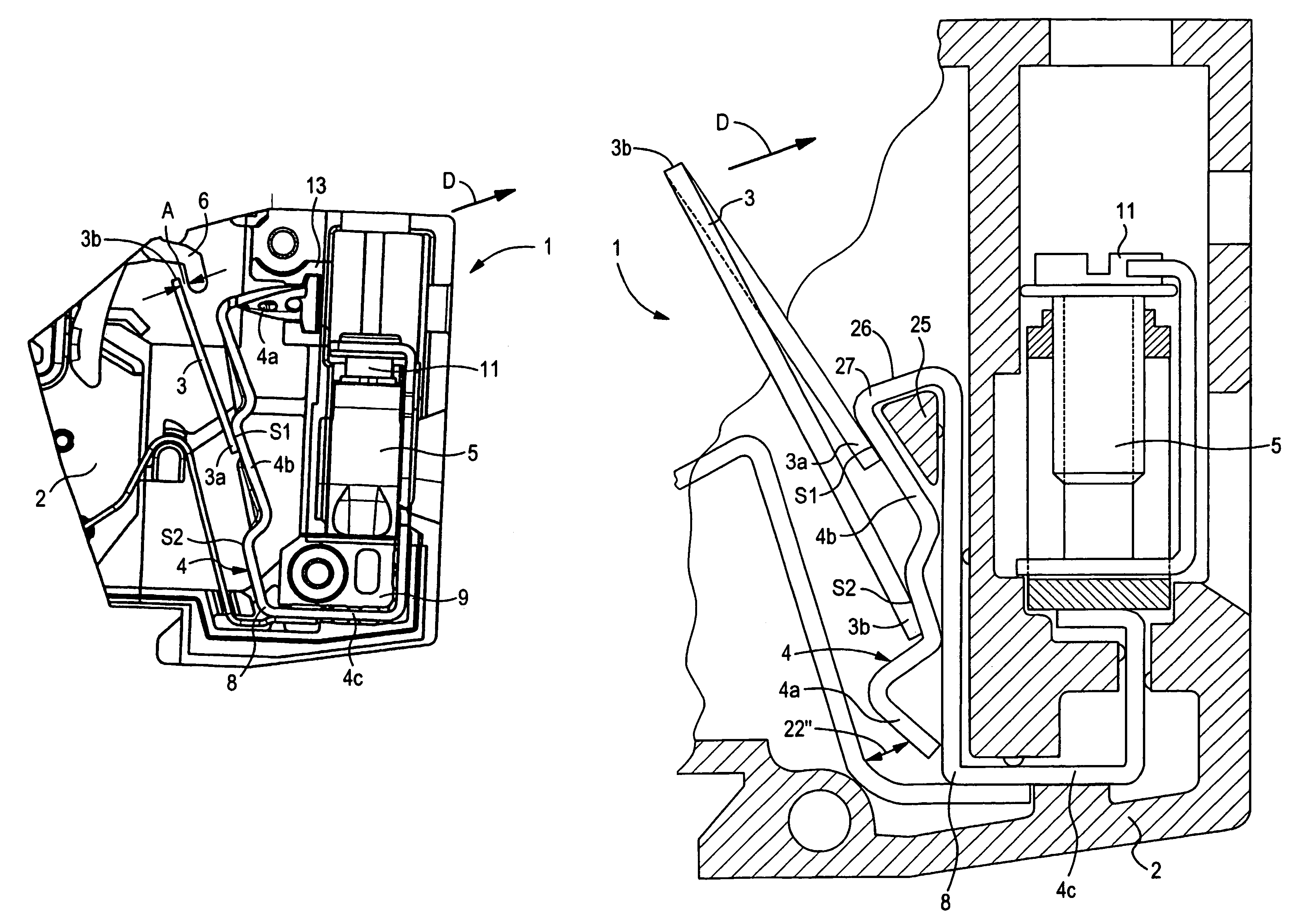
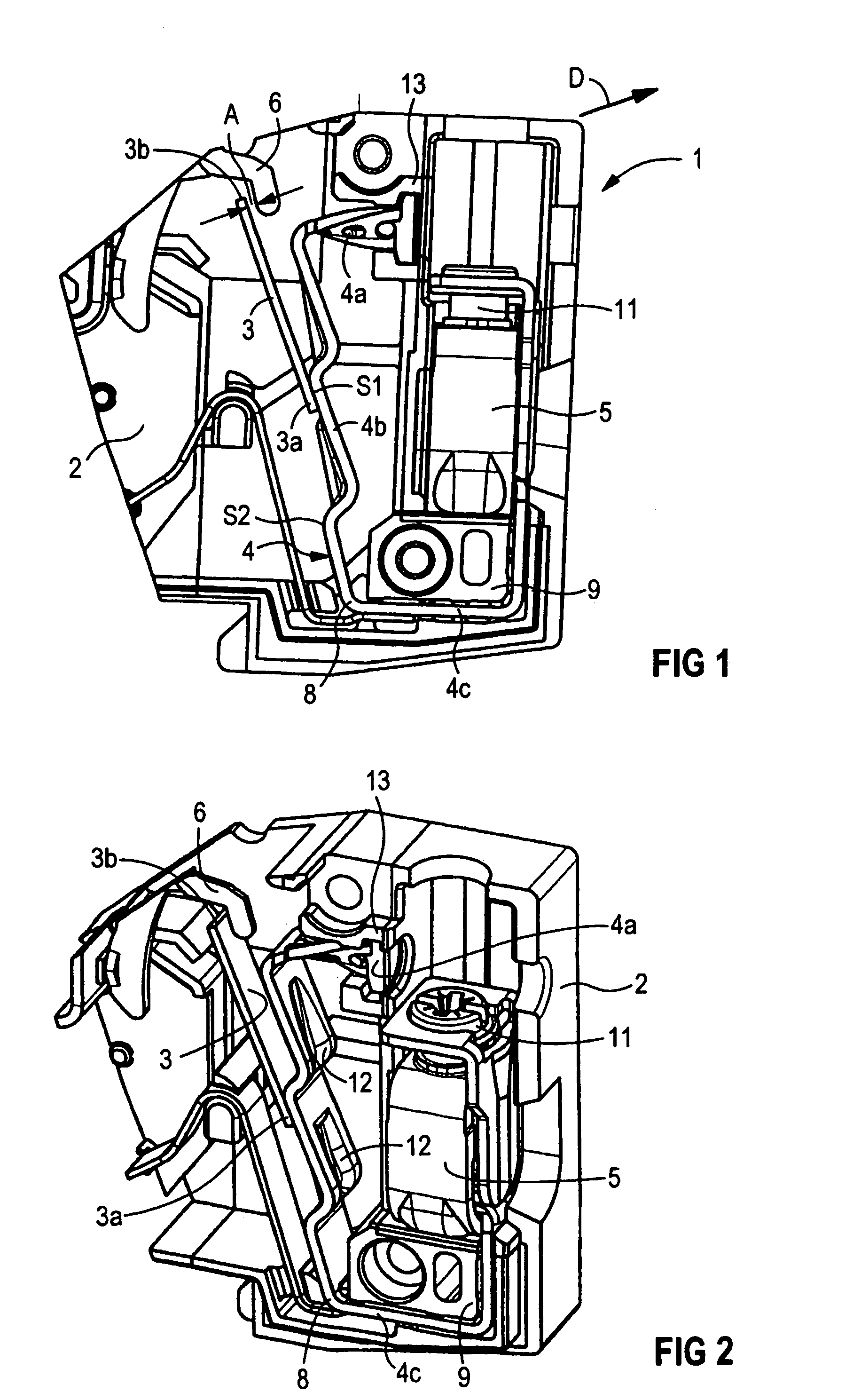
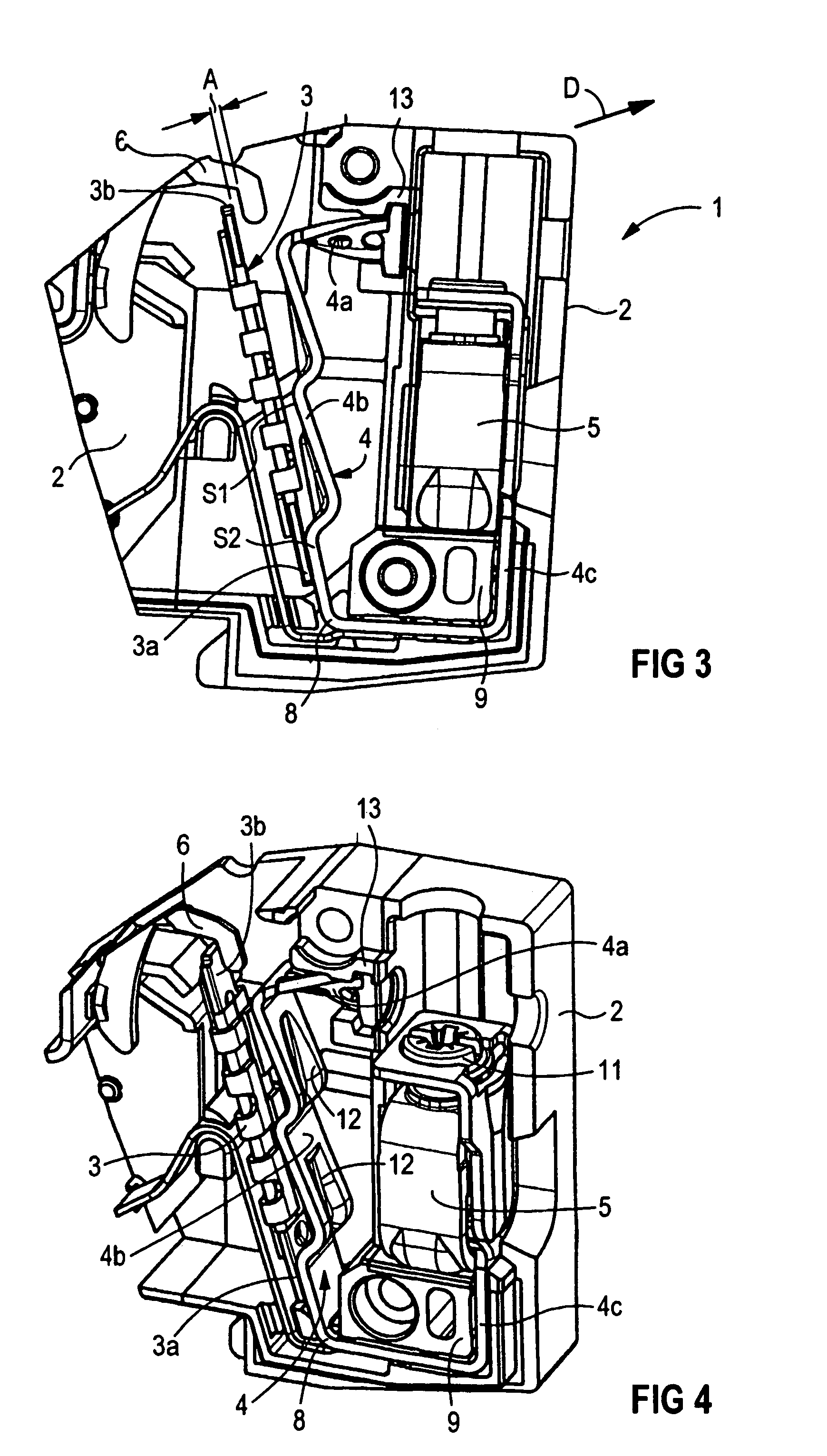
[0024]FIGS. 1 to 4 show, in the form of details, a switching device 1 with the housing cover of its housing 2 lifted off, in which the essential parts of an adjustable thermal release are shown such that they are visible. The thermal release has a bimetallic strip 3, whose contact end 3a is connected by techniques such as bonding, soldering or welding to a bimetallic strip mount 4, and is thus held in a fixed position. The bimetallic strip mount 4 is electrically conductively connected via the switching device 1 to a connecting terminal 5, in order to supply power.

[0025]The free end 3b of the bimetallic strip 3, that is to say the tip of the bimetallic strip, is opposite and at a distance from a tripping lever 6, which is coupled in a manner known per se to a switching mechanism, which is not illustrated in any more detail. This distance A between the tip of the bimetallic strip 3b and the tripping lever 6 can be adjusted by bending or deformation of the bimetallic strip mount 4.

[00...


PUM


Abstract

An adjusting device is for a thermal trip of a switchgear. It includes a bimetal, which is held in a fixed manner on a bimetal support, whose free end is located at a distance from a tripping lever, and which increasingly acts upon this tripping lever in a tripping direction as a result of thermal deformation. A distance can be adjusted by deforming the bimetal support. The adjusting device is particularly suited for use in circuit-breakers or the like.

Description

[0001]This application is the national phase under 35 U.S.C. § 371 of PCT International Application No. PCT / DE02 / 02223 which has an International filing date of Jun. 19, 2002, which designated the United States of America and which claims priority on German Patent Application numbers DE 101 31 963.0 filed Jul. 2, 2001 and DE 201 16 792.1 filed Oct. 15, 2001, the entire contents of which are hereby incorporated herein by reference.FIELD OF THE INVENTION[0002]The invention generally relates to an adjustment apparatus for a thermal release or trip for a switching device. In this case, the expression switching device refers to mechanical or electromechanical switching devices, in particular line circuit breakers, power breakers, relays, contactors or the like.BACKGROUND OF THE INVENTION[0003]An adjustment apparatus is known from EP 0 913 848 A2.[0004]A switching device is used for connecting a circuit to a power supply system and for manual and automatic disconnection of the circuit fro...

Claims


Application Information

Patent Timeline
Patent Type & Authority Patents(United States)
IPC IPC(8): H01H37/20H01H37/52H01H37/04H01H71/74
CPCH01H71/7436
Inventor LEITL, WOLFGANGWEBER, CHRISTOPH
Owner SIEMENS AG
Why Eureka
Try Eureka