
System for determining vehicular relative roll angle during a potential rollover event

a technology of relative roll angle and control apparatus, which is applied in the direction of pedestrian/occupant safety arrangement, cycle equipment, instruments, etc., can solve the problems of affecting the determination of the relative roll angle in the control system, the inability to direct measurement, and the inability to measure the roll of the vehicle. achieve the effect of improving the determination of the roll angl

Inactive Publication Date: 2006-11-14
FORD GLOBAL TECH LLC
View PDF189 Cites 15 Cited by
  • Summary
  • Abstract
  • Description
  • Claims
  • Application Information

AI Technical Summary

Benefits of technology

[0011]One advantage of the invention is that by providing such a system an improved determination of roll angle after a lifting or loading event may be determined. The amount of evasive active control actions such as braking and steering may correspondingly be increased in order to control the potential rollover in its initial trending stage such that the rollover is eventually eliminated.

Problems solved by technology

Typically, the dynamic control systems do not address roll of the vehicle.
Although the vehicle attitude is well defined, direct measurement is usually impossible.
However, the sensed relative roll angle in that system gets saturated due to various system limitations when the vehicle roll angle increases so as to cause side lifting although the actual relative roll angle of the vehicle is growing rapidly.
Although the above-cited references help model and analyze the roll dynamics during potential rollover events, they have less practical application in active rollover control implementations.
One reason is that the full car dynamics or detailed multi-body dynamics are too complicated to be implemented in feedback control algorithms.
The second reason is that the initial condition or vehicle states right before the vehicular rollover are usually unknown and sometimes might not be able to be identified through the available sensor signals.
Furthermore, certain variables used in the aforementioned analysis cannot be estimated by the available sensors.

Method used


Image

  • System for determining vehicular relative roll angle during a potential rollover event
  • System for determining vehicular relative roll angle during a potential rollover event
  • System for determining vehicular relative roll angle during a potential rollover event

Examples


Embodiment Construction

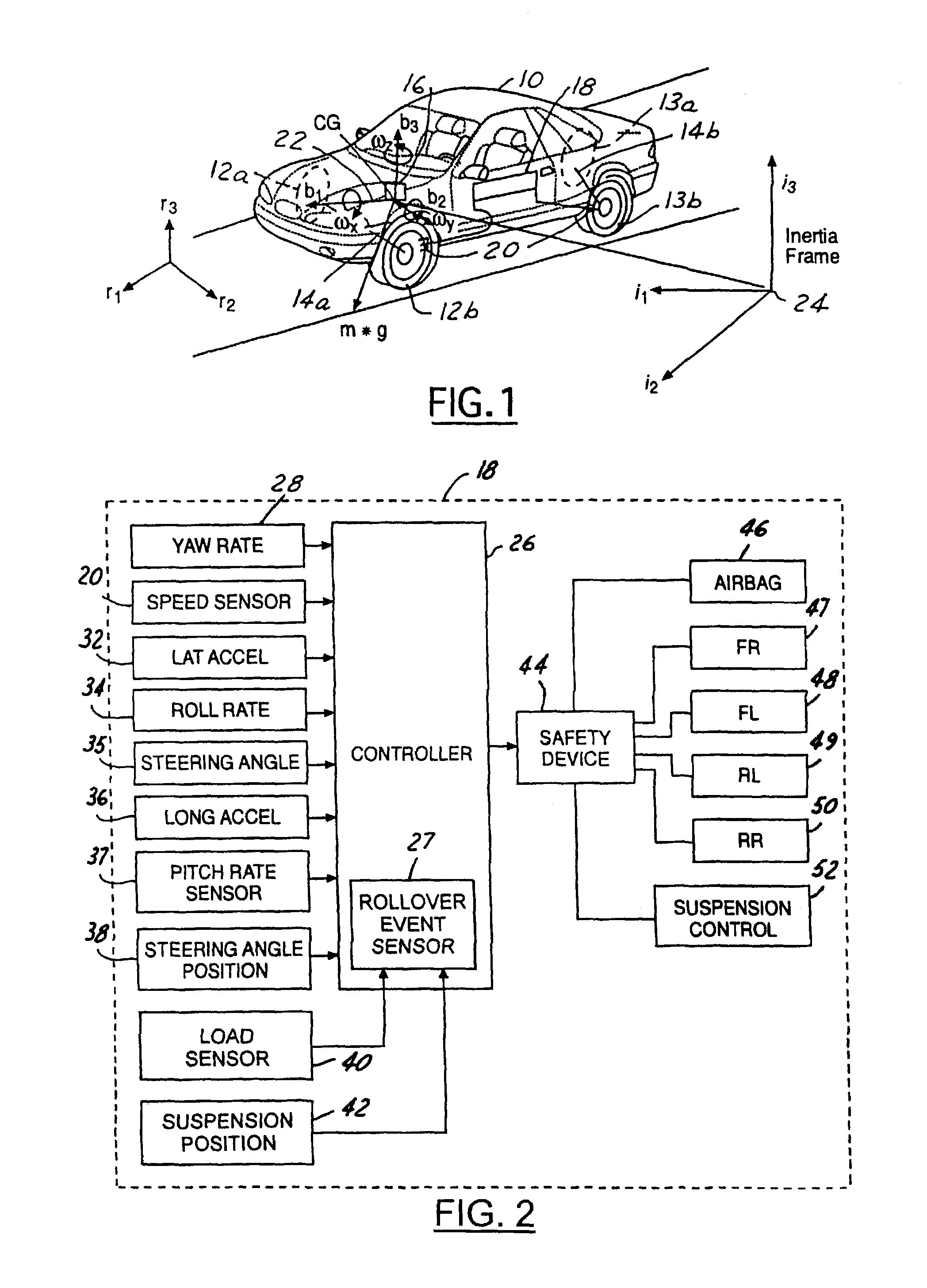
[0019]In the following figures the same reference numerals will be used to identify the same components. The present invention is preferably used in conjunction with a rollover control system for a vehicle. However, the present invention may also be used with a deployment device such as an airbag or roll bar. The present invention will be discussed below in terms of preferred embodiments relating to an automotive vehicle moving in a three-dimensional road terrain.

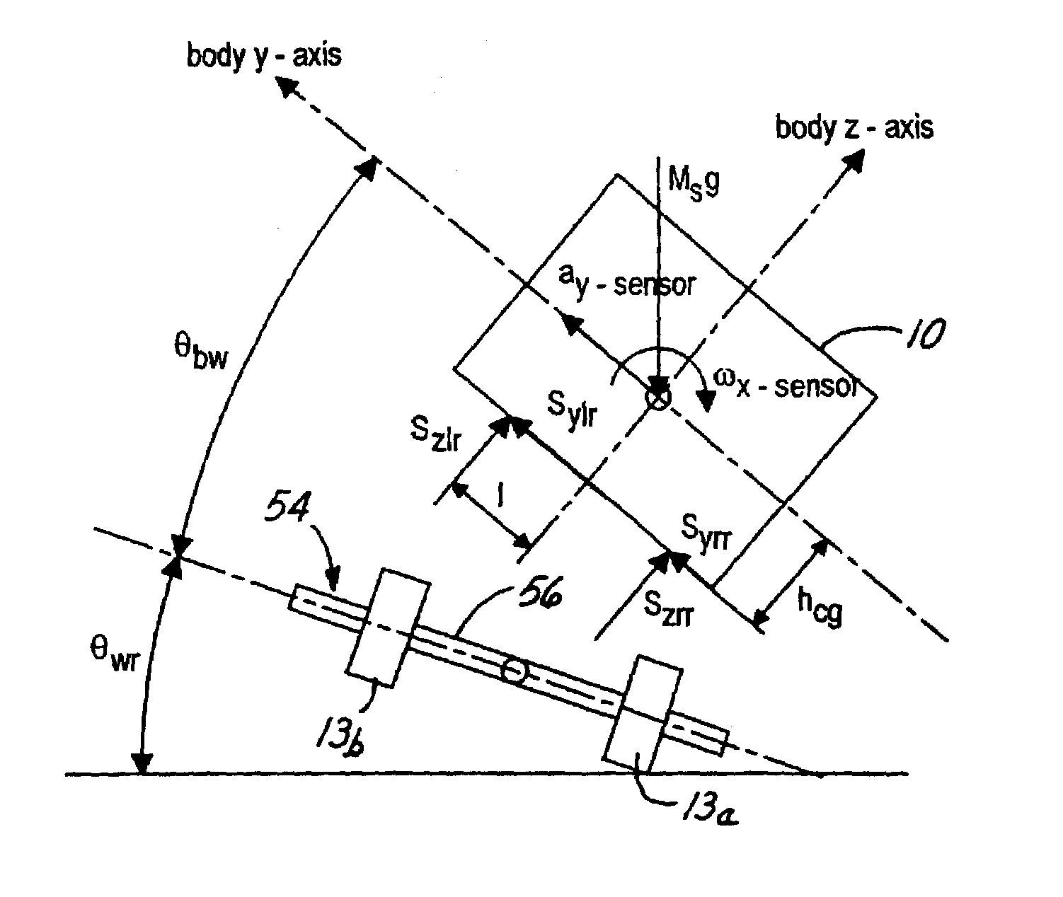
[0020]Referring to FIG. 1, an automotive vehicle 10 with a safety system of the present invention is illustrated with the various forces and moments thereon during a rollover condition. Vehicle 10 has front right and front left tires 12a and 12b and rear right tires 13a and left rear tires 13b respectively. The vehicle 10 may also have a number of different types of front steering systems 14a and rear steering systems 14b including having each of the front and rear wheels configured with a respective controllable actuator, ...


PUM


Abstract

A control system (18) for an automotive vehicle (10) has a roll angular rate sensor (34) and a lateral accelerometer (32) that are used to determine the body roll angle of the vehicle when a rollover event has been sensed. A rollover event sensor (27) may be implemented physically or in combination with various types of suspension, load or other types of lifting determinations.

Description

TECHNICAL FIELD[0001]The present invention relates generally to a control apparatus for controlling a system of an automotive vehicle in response to sensed dynamic behavior, and more specifically, to a method and apparatus for controlling the system of the vehicle by determining the roll angle of the vehicle relative to the road surface.BACKGROUND OF THE INVENTION[0002]Dynamic control systems for automotive vehicles have recently begun to be offered on various products. Dynamic control systems typically control the yaw of the vehicle by controlling the braking effort at the various wheels of the vehicle. Yaw control systems typically compare the desired direction of the vehicle based upon the steering wheel angle and the direction of travel. By regulating the amount of braking at each corner of the vehicle, the desired direction of travel may be maintained. Typically, the dynamic control systems do not address roll of the vehicle. For high profile vehicles in particular, it would be...

Claims


Application Information

Patent Timeline
IPC IPC(8): G06F19/00B60R16/02B60R16/023B60R21/01B60R21/013B60R21/0132B60T8/172G06F17/00
CPCB60R16/0233B60R21/0132B60T8/172B60W10/18B60W10/20B60W10/22B60W30/04B60R2021/01313B60R2021/01327B60T2230/03B60T2240/06B60W2510/20B60W2520/105B60W2520/125B60W2520/14B60W2520/18B60W2540/18
Inventor LU, JIANBOMATTSON, KEITH GLENNBROWN, TODD ALLEN
Owner FORD GLOBAL TECH LLC
Learn More