Filter element

Inactive Publication Date: 2006-11-21
MANN HUMMEL GMBH
View PDF12 Cites 102 Cited by
  • Summary
  • Abstract
  • Description
  • Claims
  • Application Information

AI Technical Summary

Benefits of technology

[0007]It is the object of the invention to provide a filter element of the type described above such that the fi

Problems solved by technology

In such case, the supporting layer has no influence on the filtration proper

Method used


Image

  • Filter element
  • Filter element
  • Filter element

Examples


Embodiment Construction

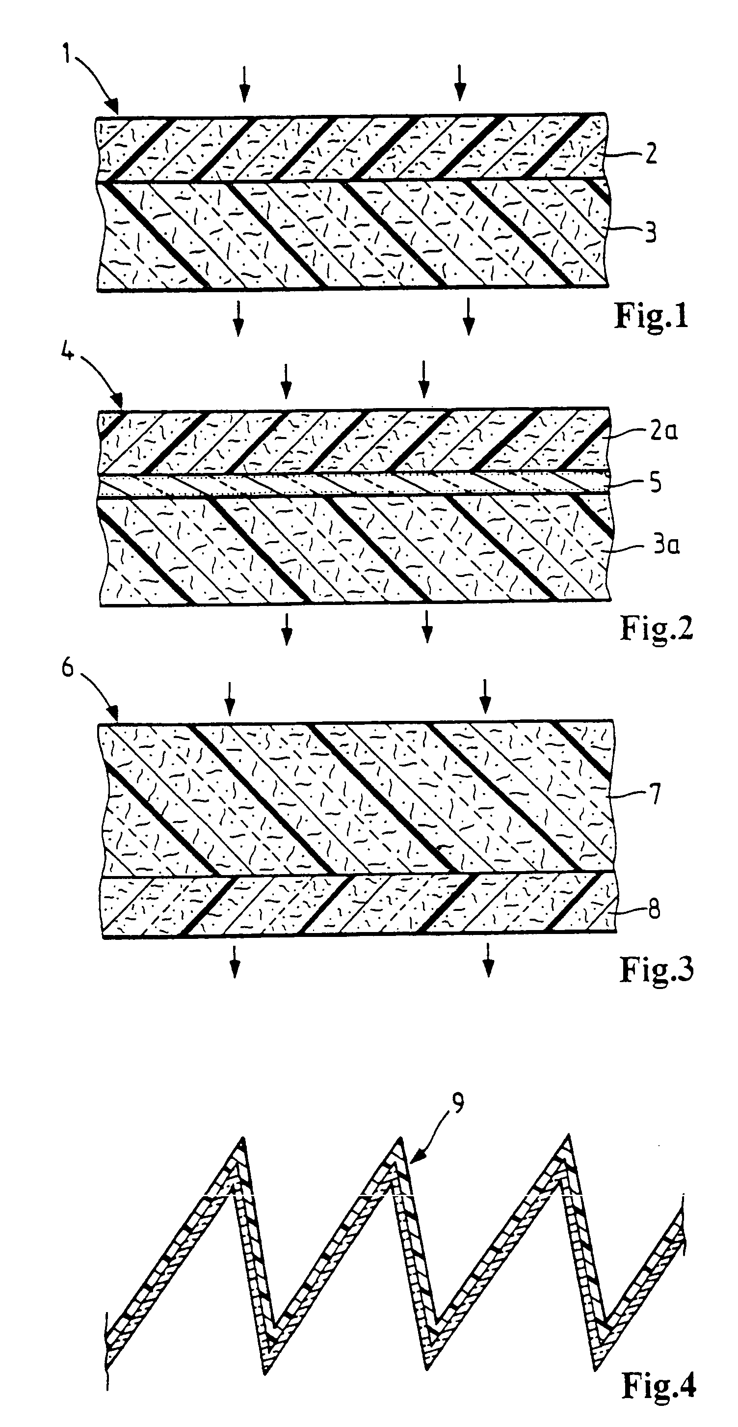
[0028]FIG. 1 shows a section through a filter element 1 with an inflow-side layer 2 of melt-blown nonwoven fleece and an outflow-side layer 3 of cellulose-containing filter paper. The melt-blown nonwoven fleece of layer 2 can be made for example with a fiber material having a weight per unit area of about 15 to 150 g / m2 and on the outflow-side layer 3 can be made with cellulose-containing filter paper having a weight per unit area of approximately 50 to 200 g / m2.

[0029]The starting material for the melt-blown nonwoven web may be, for example, PP (polypropylene), especially for non-aggressive fluids, or PES (polyethersulfone).

[0030]In an embodiment of a filter element 4 according to FIG. 2, a third layer 5 of a calendared melt-blown material is arranged between the inflow-side layer 2 and the outflow-side layer 3.

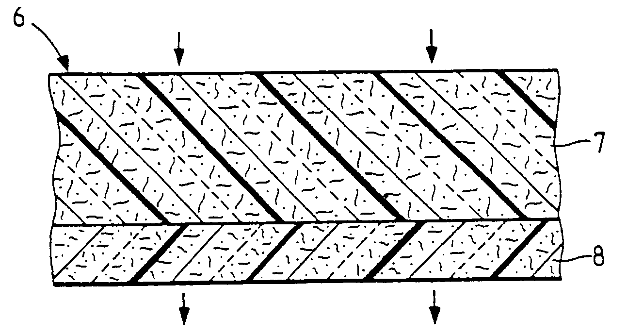
[0031]Another preferred embodiment of a filter element 6 is illustrated in FIG. 3. Here the inflow-side filter medium is composed of a layer 7 of a cellulose-containing filte...


PUM

PropertyMeasurementUnit
Lengthaaaaaaaaaa
Fractionaaaaaaaaaa
Areaaaaaaaaaaa

Abstract

A filter element in which several layers (2, 3, 5, 7, 8) made of a filtering medium are joined contiguously in the direction of flow with at least one layer (2, 7) made of a filtering medium with a high storage capacity and a low degree of separation being arranged on the in-flow side and at least one layer (3, 8) made of a filtering medium with a low storage capacity and a high degree of separation being arranged on the out-flow side. Preferably the in-flow filtering medium is made of a filter paper containing cellulose or of a melt-blown material, and the out-flow side filtering medium is produced from a filter paper containing cellulose.

Description

BACKGROUND OF THE INVENTION[0001]The invention relates to a filter element especially for filtering fluids.[0002]It is known that different types of filter material can be used in known filter elements, combined to produce an optimum filter behavior for the particles to be filtered out and the fluid flowing through. For example, it is known from DE 44 43 158 A1 to use a melt-blown material as the filter medium in a gas stream together with a carrier material serving exclusively for stabilization.[0003]It is also known from WO 96 / 34673 to locate a plurality of filter layers made of a melt-blown material on a carrier layer in a hollow cylindrical filter element. The layers then form together a replaceable filter element that can be placed in a filter system.[0004]The sequential arrangement of nonwoven filter media made of synthetic fibers with staggered filter fineness is known from U.S. Pat. No. 5,496,627 and WO 95 / 17946, with the filter fineness of the filter layers increasing in th...

Claims


Application Information

Patent Timeline
IPC IPC(8): B01D39/18B01D29/01B01D39/16B01D39/20
CPCB01D29/012B01D39/1623B01D39/18B01D39/2017B01D29/016Y10T442/68Y10T442/693B01D39/16
Inventor KLEIN, GUNNAR-MARCELMOSER, NIKOLAUS
Owner MANN HUMMEL GMBH
Why Eureka
Try Eureka