
Tilting mast in a rotorcraft

a rotorcraft and tilting technology, applied in the field of rotary wing aircraft, can solve the problems of large and sometimes undesirable fuselage attitudes, undesirable attitudes, and the helicopter's fuselage also tilting nose down, and achieve the best lift-to-drag ratio, reduce parasitic drag, and reduce the effect of rotor lift requirements

Active Publication Date: 2006-11-21
JAUNT AIR MOBILITY LLC
View PDF21 Cites 41 Cited by
  • Summary
  • Abstract
  • Description
  • Claims
  • Application Information

AI Technical Summary

Benefits of technology

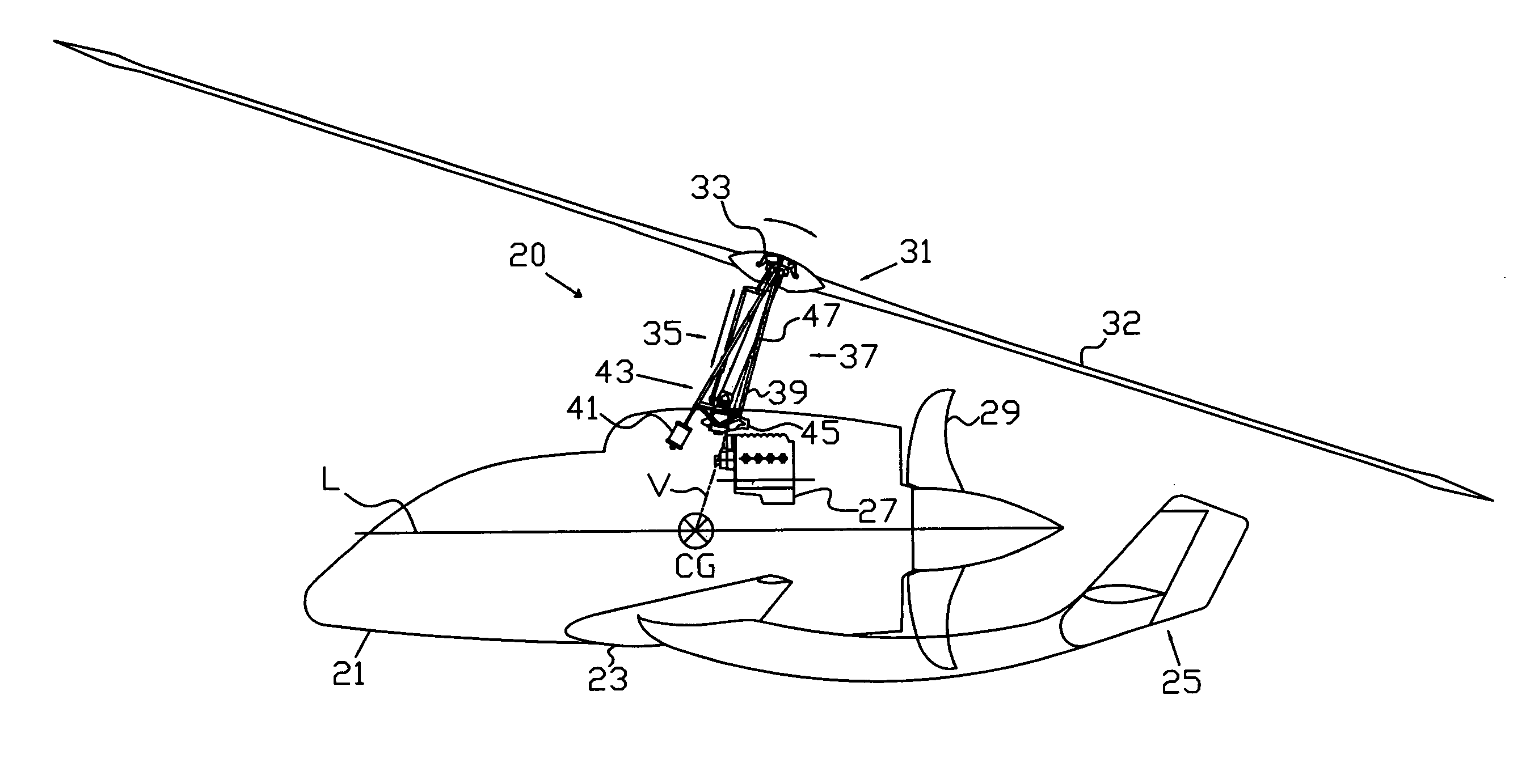
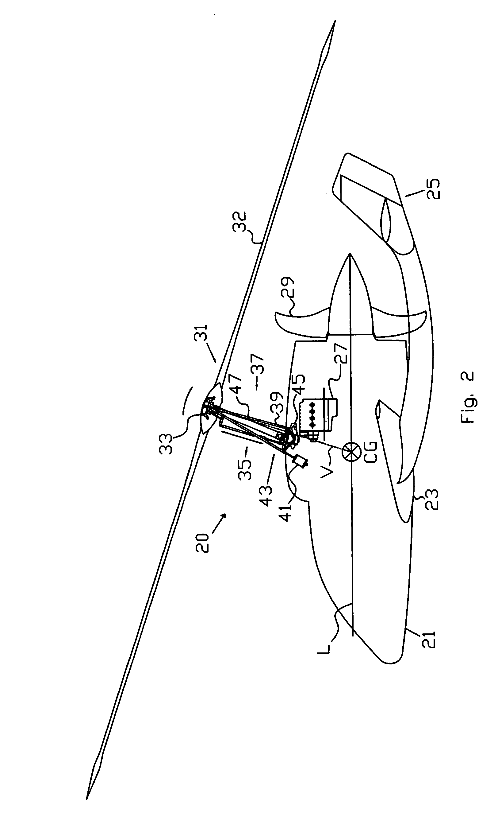
[0012]In view of the foregoing, embodiments of the present invention advantageously provide an aircraft including an aircraft rotor assembly that eliminates the design and flying problems and concerns caused by fuselage attitude changes in the helicopter, autogyro, compound helicopter, and gyroplane, by tilting the rotor mast. Embodiments of the present invention provide a means to manipulate a rotor such that the resultant force vector is maintained at or near the aircraft center gravity to prevent excessive moments causing excessive fuselage pitching, especially in slow speed flight and during acceleration and deceleration.
[0016]In an embodiment of the present invention, a cyclic pivot location and a tilting mast frame pivot location are such that the cyclic control linkage can maintain the rotor resultant force vector through or near the aircraft center of gravity during tilting of the tilting mast. More specifically, in the preferred configuration, the cyclic control linkage is positioned such that the angular movement of the tilting mast frame is slightly less than the angular movement of the spindle during tilting of the tilting mast.
[0018]In an embodiment of the present invention, the tilting of the mast can be accomplished through automated means. In this embodiment, a controller can receive input from an airspeed sensor and an angle of attack sensor to control the mast tilt to keep the fuselage at a desired pitch. This is especially useful in an gyroplane at low speeds in order to keep the wing at an angle of attack for a best lift-to-drag ratio. Additionally, the controller can tilt the tilting mast frame and cyclic control together to a predetermined position. This feature is particularly useful in a gyroplane at high speeds as rotor lift requirements decrease. Additionally, the controller can tilt the tilting mast frame and the cyclic control together during cruise and during landing as necessary to keep the fuselage substantially level, or at some desired pitch. This feature is particularly useful during cruise flight to reduce parasitic drag and during landing to eliminate the need for a large flare. Also, the controller can tilt the tilting mast frame and cyclic control together during flight to accommodate for in flight CG changes.

Problems solved by technology

The resultant force vector, however, must remain close to the aircraft center of gravity with the result that the helicopter's fuselage also tilts nose down.
Further, the combined effects of forward speed and this tendency for the resultant force vector to pass through the center of gravity, can cause large and sometimes undesirable fuselage attitudes in steady flight.
These undesirable attitudes are especially prevalent in helicopter designs where the mast of the rotor head has a preset forward tilt implemented to provide the aircraft fuselage with a more level attitude during cruise flight.
Applicant recognizes that the above described fuselage attitudes of both helicopters and autogyros are sometimes uncomfortable to the occupants, and / or can cause loss of pilot visibility, and / or cause difficult and dangerous landing conditions.
The winged helicopter and the winged autogyro, however, when in autorotation, can encounter excessive nose-up fuselage attitude in slow speed flight and / or flares, which will stall the wing.

Method used


Image

  • Tilting mast in a rotorcraft
  • Tilting mast in a rotorcraft
  • Tilting mast in a rotorcraft

Examples


Embodiment Construction

[0027]The present invention will now be described more fully hereinafter with reference to the accompanying drawings which illustrate embodiments of the invention. This invention may, however, be embodied in many different forms and should not be construed as limited to the illustrated embodiments set forth herein. Rather, these embodiments are provided so that this disclosure will be thorough and complete, and will fully convey the scope of the invention to those skilled in the art. Like numbers refer to like elements throughout, and the prime notation, if used, indicates similar elements in alternative embodiments.

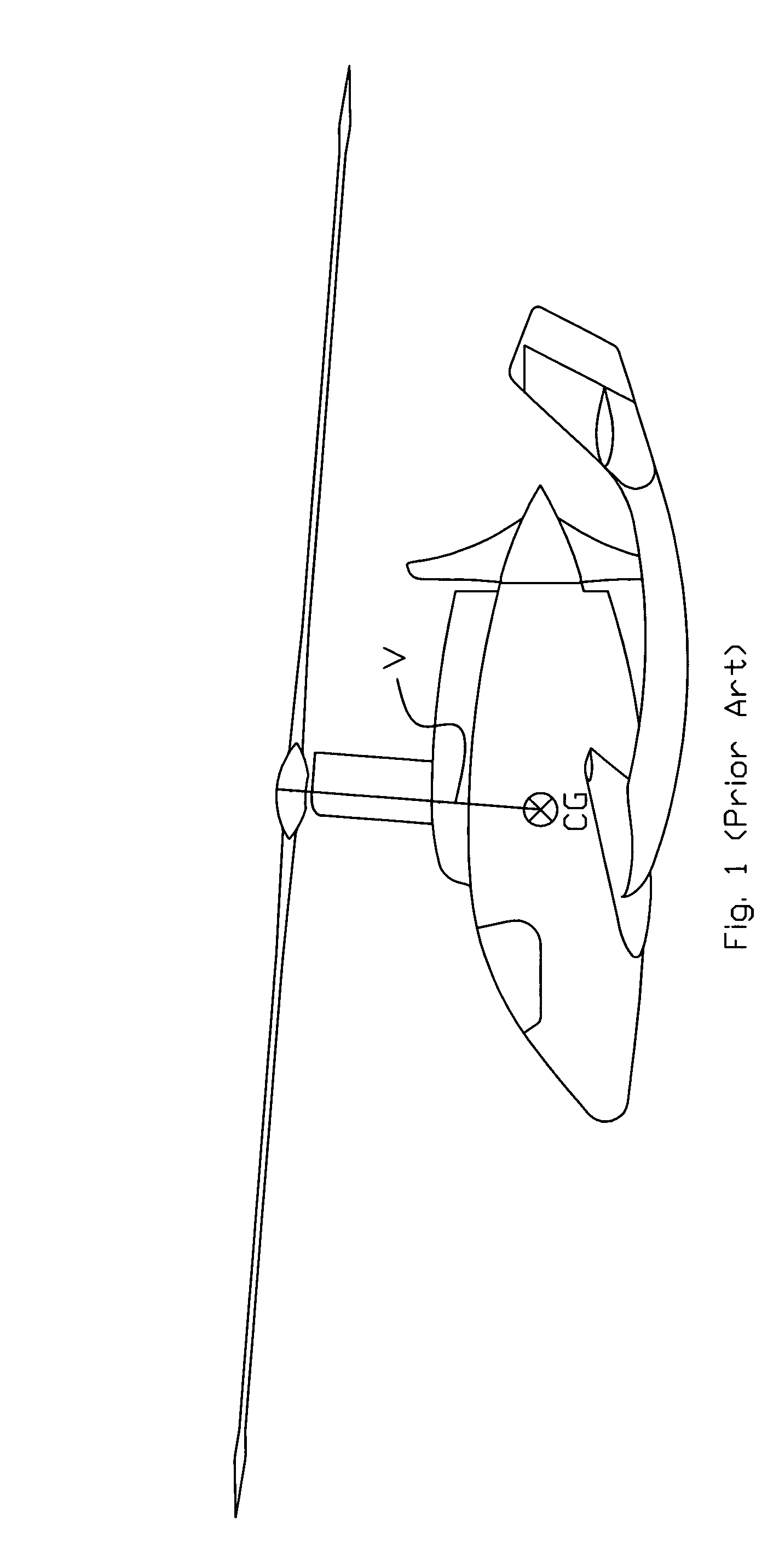
[0028]Referring to FIG. 1, shown is a simplified model of a conventional fixed mast in a rotorcraft having a longitudinal axis passing through or near the design gross weight, and design configuration, aircraft center of gravity CG. The rotorcraft or rotary wing aircraft has blades that rotate to describe or form a plane of rotation (“rotor disc”) and which produces a re...


PUM


Abstract

A rotorcraft includes a fuselage, a rotor assembly, a tail section connected to the fuselage, a propulsion system including an engine mounted to the fuselage, and a wing mounted to the fuselage. The rotor assembly includes a rotor having either a single or a plurality of rotor blades which can produce a resultant force vector which can pass through or near the center of gravity of the rotorcraft, and a spindle to connect the rotor with a flight control assembly. The rotor assembly also includes a tilting mast assembly having a tilting mast frame also connected to the spindle to support the rotor. The tilting mast tilts the rotor and provides cyclic control through a cyclic control linkage connected to the tilting mast frame. A mast control cylinder is provided to tilt the tilting mast assembly.

Description

RELATED APPLICATIONS[0001]This application claims priority from provisional application Ser. No. 60 / 448,305, titled “Tilting Mast In A Rotorcraft,” filed on Feb. 19, 2003.BACKGROUND OF THE INVENTION[0002]1. Field of the Invention[0003]The present invention relates generally to rotary wing aircraft. In more specific aspects, the present invention relates to the mast that supports the rotary wing system of a rotary wing aircraft and methods for use associated therewith.[0004]2. Description of the Related Art[0005]There are two types of heavier-than-air aircraft that achieve lift by movement through the air that relate to this art: (1) the airplane, and (2) the rotorcraft or rotary wing aircraft. The airplane has stationary wings that create lift when propelled through the air by a thrust mechanism such as a propeller or jet engine. The rotorcraft or rotary wing aircraft has blades that rotate to describe or form a rotor disc (the plane the rotor blades rotate in) positioned above the ...

Claims


Application Information

Patent Timeline
IPC IPC(8): B64C27/00B64C27/52
CPCB64C27/52
Inventor CARTER, JAY W.MITCHELL, GEORGE D.
Owner JAUNT AIR MOBILITY LLC
Learn More