

Gear pump with variable throughput volume
- Summary
- Abstract
- Description
- Claims
- Application Information
AI Technical Summary
Benefits of technology
Problems solved by technology
Method used
Image

Examples
Embodiment Construction
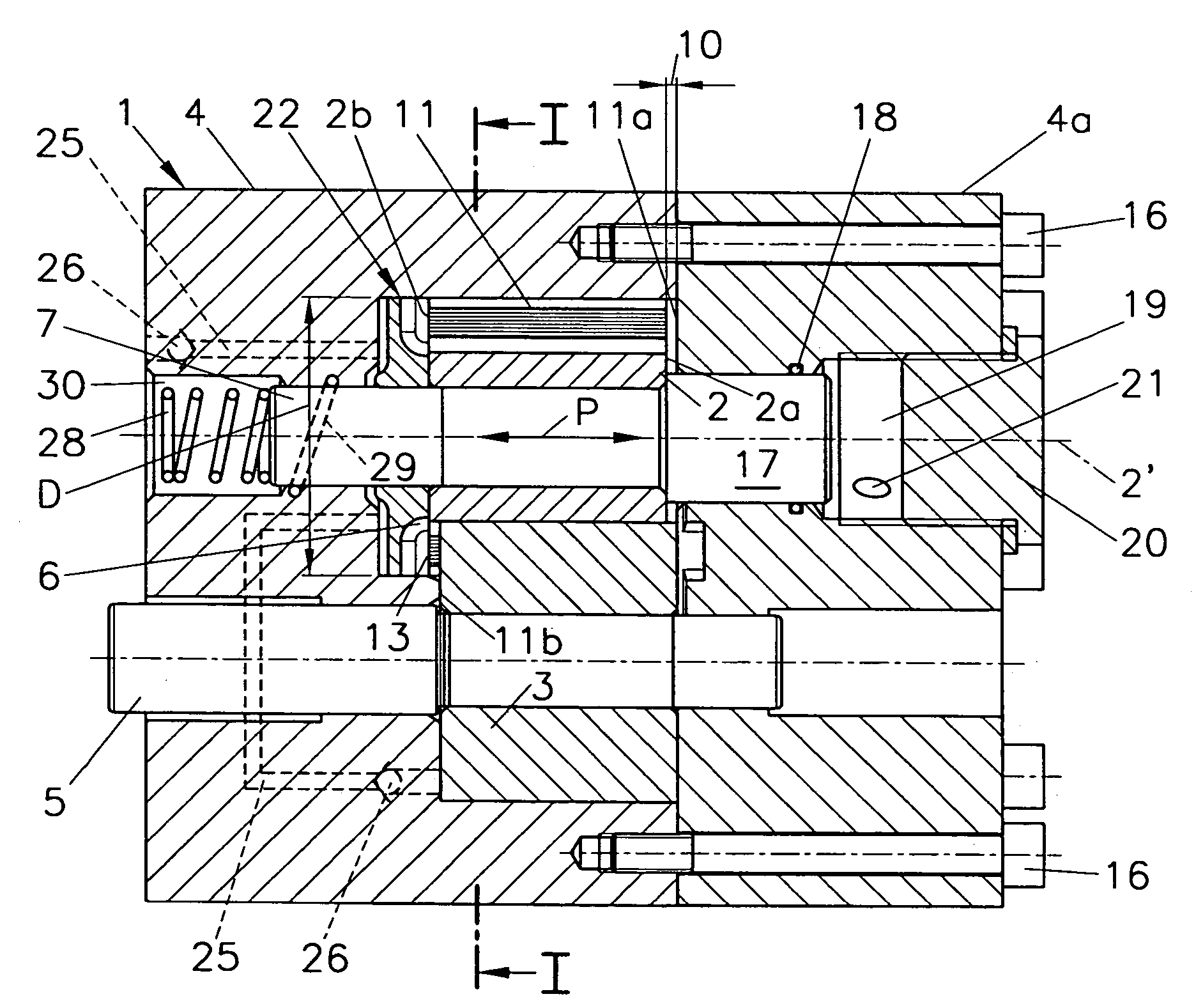
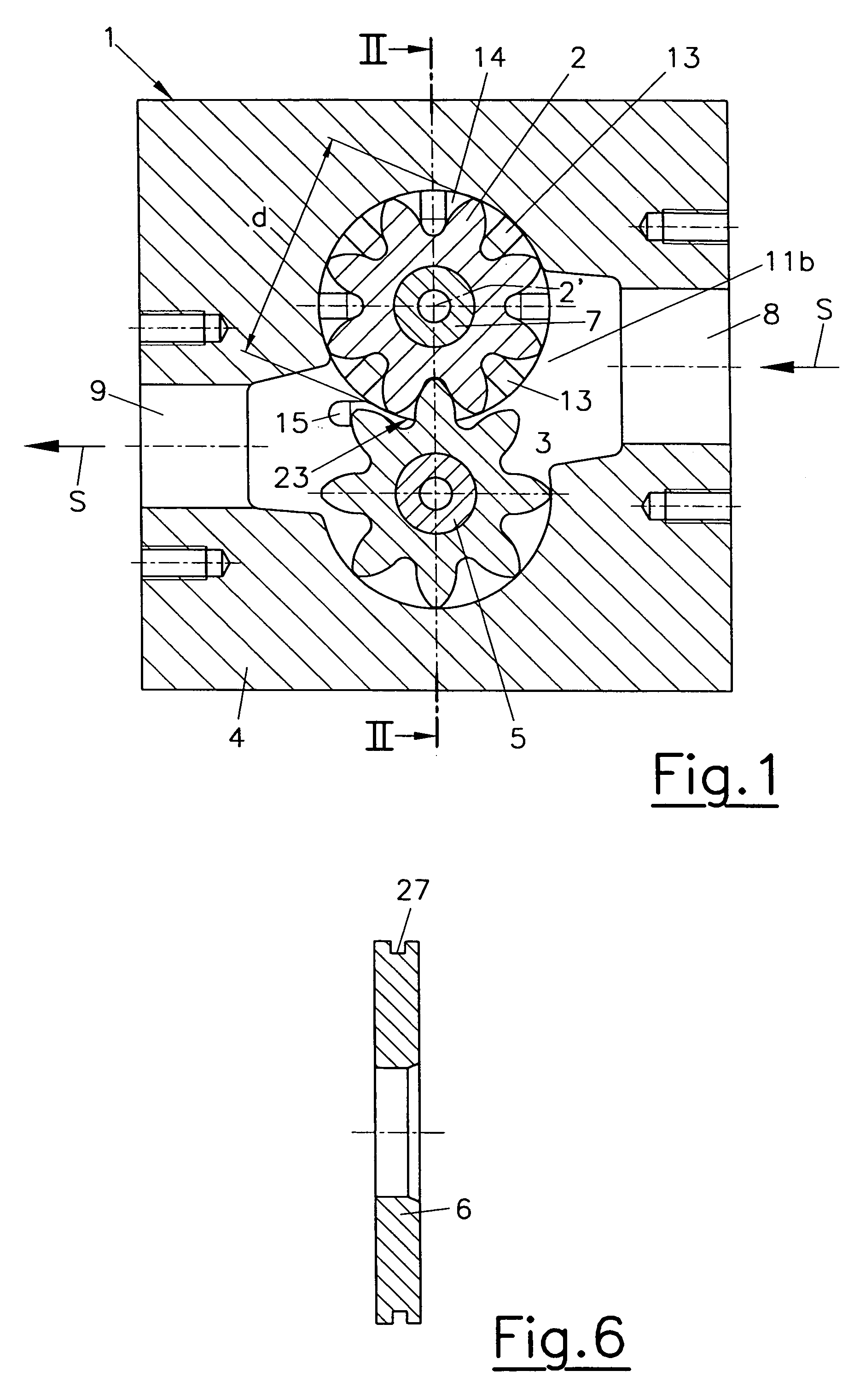
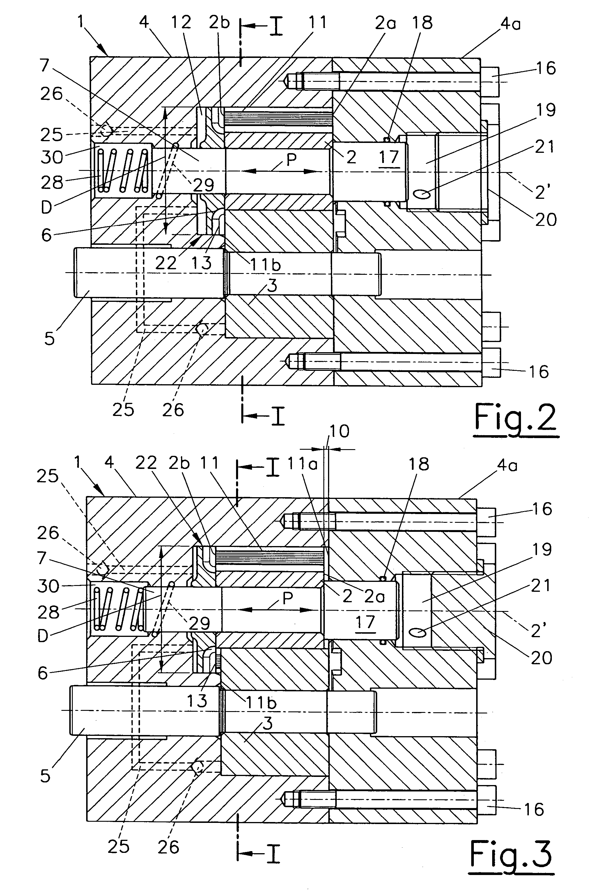
[0023]The gear pump 1 has two externally toothed meshing gears 2, 3 which are rotatably held in the working chamber 11 of a pump housing 4. The gear 3 is driven by a drive shaft 5 and in turn drives the gear 2. The driven gear 2 is mounted, together with a sealing plate 6, on a control shaft 7 and can be shifted in the direction of the axis 2′ of the gear 2 together with the shaft 7, as indicated by the arrow P. Reference number 8 indicates the suction side, reference number 9 the pressure side of the gear pump 1 and the arrows S show the flow direction of the medium.
[0024]By shifting the control shaft 7 and thus the shiftable gear 2 the gap-width 10 as shown in FIG. 3 may be altered. The gap-width 10 is defined as the distance between a plane first interior side wall 11a of the working chamber 11 of the pump housing 4 and a first front face 2a of the shiftable gear 2. With d denoting the outer diameter of the gear 2, the range of adjustment of the gap-width 10 is between 0 and d / 5,...
PUM
 Abstract
Description
Claims
Application Information