
Set of surgical instruments for the fixation of vertebrae

a surgical instrument and set technology, applied in the field of set of surgical instruments, can solve the problems of affecting the recovery of patients, and the inability to solve the “hidden” of the built-in structural elements in every case, so as to reduce the risk of complications, reduce the burden of operation, and facilitate the patient's recovery. effect of speed

Inactive Publication Date: 2006-11-21
SANATMETAL
View PDF8 Cites 3 Cited by
  • Summary
  • Abstract
  • Description
  • Claims
  • Application Information

AI Technical Summary

Benefits of technology

[0020]With the creation of the surgical instruments disclosed herein, the aim was to overcome the faults of the known versions and to create a construction with the help of which, in a short operation time and using a small number of components, one could realize vertebral fusion that would be more stable and more durable than that achieved by the known methods with respect to any section of the spinal column, independent of the location of the injury.
[0021]The basic idea of the invention was formed by the recognition that, if screws with formed heads and unique geometry are used and the connection unit is formed innovatively by a group of flexible strands that are easily deformed on their own, and that can be handled individually and grouped in the desired amount, then the task can be solved. During experiments, it was realised that, if the thin strands that can be easily formed on their own are bound together in an appropriately formed head in a new way, then they, together, may form a sufficiently rigid connection part, ruling out deformation and fatigue.
[0027]The instruments according to the invention have numerous advantageous features. The most important of these is that, with the use of the supporting elements that have a uniquely formed head part or unit and the novel connecting unit, the approach for the surgery can be significantly reduced and can be carried out quickly using simpler instruments, with the use of few components and auxiliary equipment and without especially burdening the patient. This significantly reduces the operation burden and the danger of possible complications, and greatly aids the faster recovery of the patient.
[0028]Another advantage is that the components that are different from those traditionally used may be used along the whole length of the spinal column, both in the dorsal and lumbar sections. Moreover, a system may be set up that is not overly rigid and is formed according to the patient's build and the type of injury.
[0029]Also favourable is that, in addition to the easy formability of the elemental connection strands, the whole connecting unit has the required amount of rigidity and is still more flexible than the traditional bridging elements, so that deformation, breakage or fatigue will not occur in the case of any single component. This further reduces risk following the operation.
[0030]Still another advantage is that the elements of the instruments may be easily manufactured, easily handled and sterilised.

Problems solved by technology

The disadvantage of the known solutions, however, is that the longitudinal sizes of the usual supporting elements and the fixating devices are complex and, due to the structure that results in significant dimensions, the operation is more difficult and the “hiding” of the built-in structural elements cannot be solved in every case.
Another disadvantage is that, with the traditional assemblies, where the elements are rigid, when the patient moves, the supporting elements may become deformed or, in extreme cases, broken at which time the fixation of the vertebra is terminated.
The restoration of the desired condition may only be solved with a further operation that causes a significant burden for the patient.
A further deficiency of the known versions is that the normally used screw fixating connection device is susceptible to fatigue, and the replacement of the faulty element and the correction of the fixture also require a further surgical intervention.
Another unfavourable aspect is that, in the case of spine implants that bridge over more than two vertebrae, the appropriate planar and spatial connections of the supporting elements and connection bodies cause great difficulty, require a great number of special instruments and auxiliary equipment, and also significantly increase the duration of the operation, which not only increases the burden on the patient, but also unjustifiably increases the possibility of complications during the operation.
A further aspect that has to be treated as a disadvantage is that, in the case of traditional solutions in different sections of the spinal column, supporting elements of differing sizes and different instruments have to be used, which makes the fast and efficient performance of the operation even more difficult.
The significant disadvantage of this structure, however, is that the dimensions of the accepting seat, of the cleft leading to it, and of the connection part-unit are essentially equal, and so only a single, thick cross-section, less deformable, rod-like connection unit can be fixed into the head part of the supporting element.
Such a connection system does not provide a sufficiently flexible connection possibility between the supporting elements.
Another disadvantage is that, due to the geometric dimensions of the head part of the supporting element presented above, the connection part-unit is difficult to handle and is difficult to fix into the accepting seat of the head part.
Therefore, the connection part-unit has to be fixed into the head part of the supporting element immediately following positioning, which, however, makes the fine setting of the connection part-unit and the positioning of the supporting elements more complicated.
However, a significant disadvantage is that, due to the fixing together of the wires, putting them into the supporting elements and fixing them is complex since, due to the joint movement of the wires here also, the cleft leading into the fixing hollow essentially has to comply with the cross-section size formed by the wires altogether.
As a result of this, this arrangement also does not solve the problem of easy handling and simpler fixing.
The greatest disadvantage of the above solution is that, due to the compulsory use of the six fixing screws and the pre-shaped, bent linking and clamping elemental strands, it can only be used in certain cases and in the case of the linking together of a restricted number of vertebrae.
Therefore, its area of use is significantly limited, and it is not suitable for carrying out general vertebrae fixing tasks.
However, this gives an almost impossible task to the operator due to the unique bone structure of the individual.
Due to these significant disadvantages, this solution has not become widespread.
Another disadvantage is that all of the pre-bent elemental strands are to be used during the fixing, so that a flexible fix adapting to the patient's form and loading cannot be set up.
A significant disadvantage is that keeping the elemental strands of the connection part-unit in the seating that goes through the head part is difficult due to the outward-facing, wide cleft, which makes the job of the operator significantly more difficult, and which may increase the duration of the operation to a large extent, which is unfavourable from the point of view of the patient.
There is no possibility of such help due to the small area of the operation and the circumstances that present themselves during surgery, e.g. bleeding and reducing bleeding.
Another disadvantage that can be listed here is that the fixing of the fixing screws is in every case determined by the form and size of the vertebrae, so that, in general, the six fixing screws become positioned at varying heights and angles.
In practice, this cannot be solved.
Another significant disadvantage is that the elements carrying out the cross-linking between the fixing screws result in such rigidity that, in the case of porous vertebrae, this can in some cases lead to the pulling out of the fixing screw.
A further disadvantage of the wide and deep straight cleft forming the seating leading through the head part is that, on the one hand, it increases the dimensions of the head part, which may be a source of further accidents following the operation, and, on the other hand, it reduces the solidity of the head part, which provides an unjustified restriction on occurring loads.

Method used


Image

  • Set of surgical instruments for the fixation of vertebrae
  • Set of surgical instruments for the fixation of vertebrae

Examples


Embodiment Construction

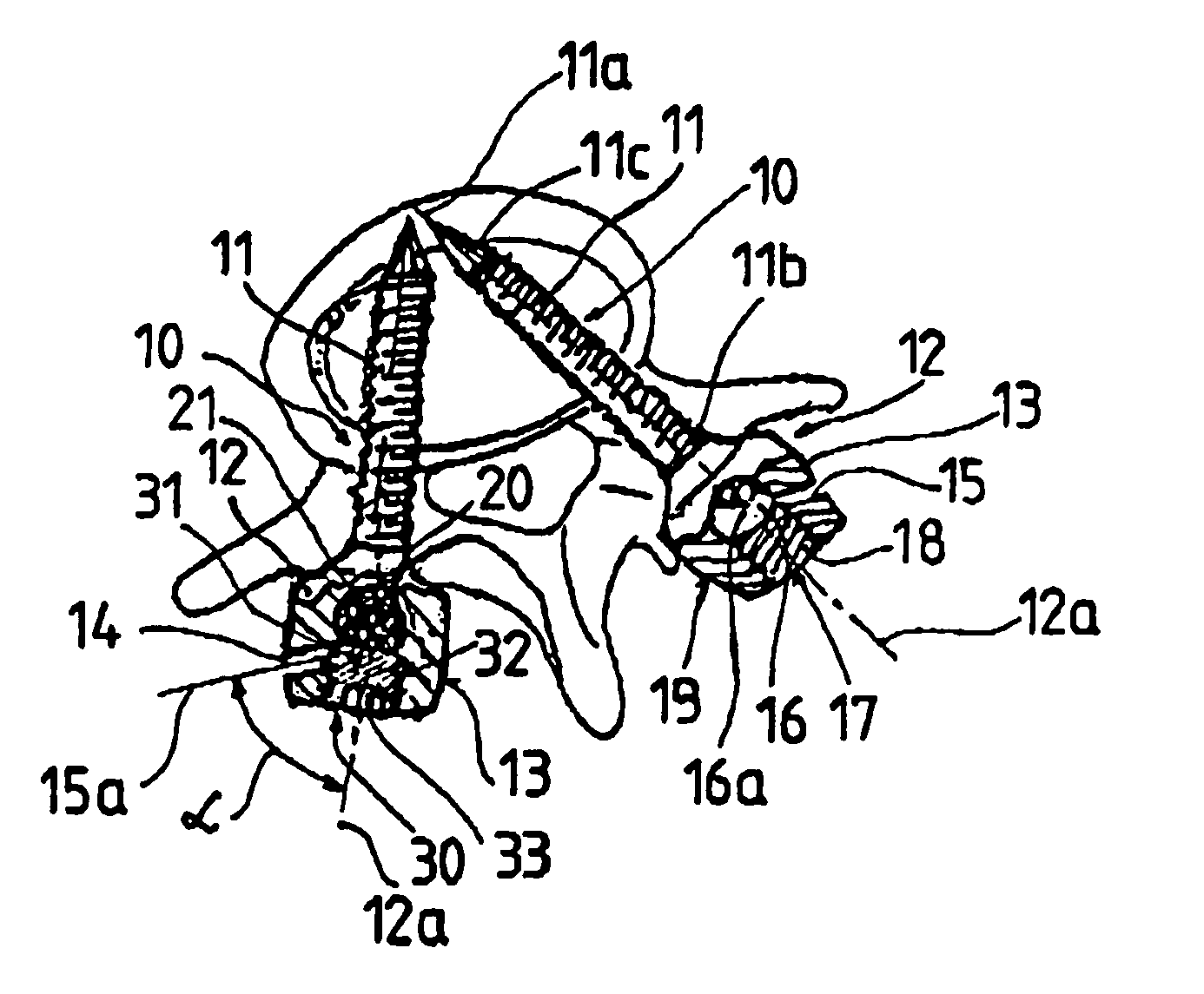
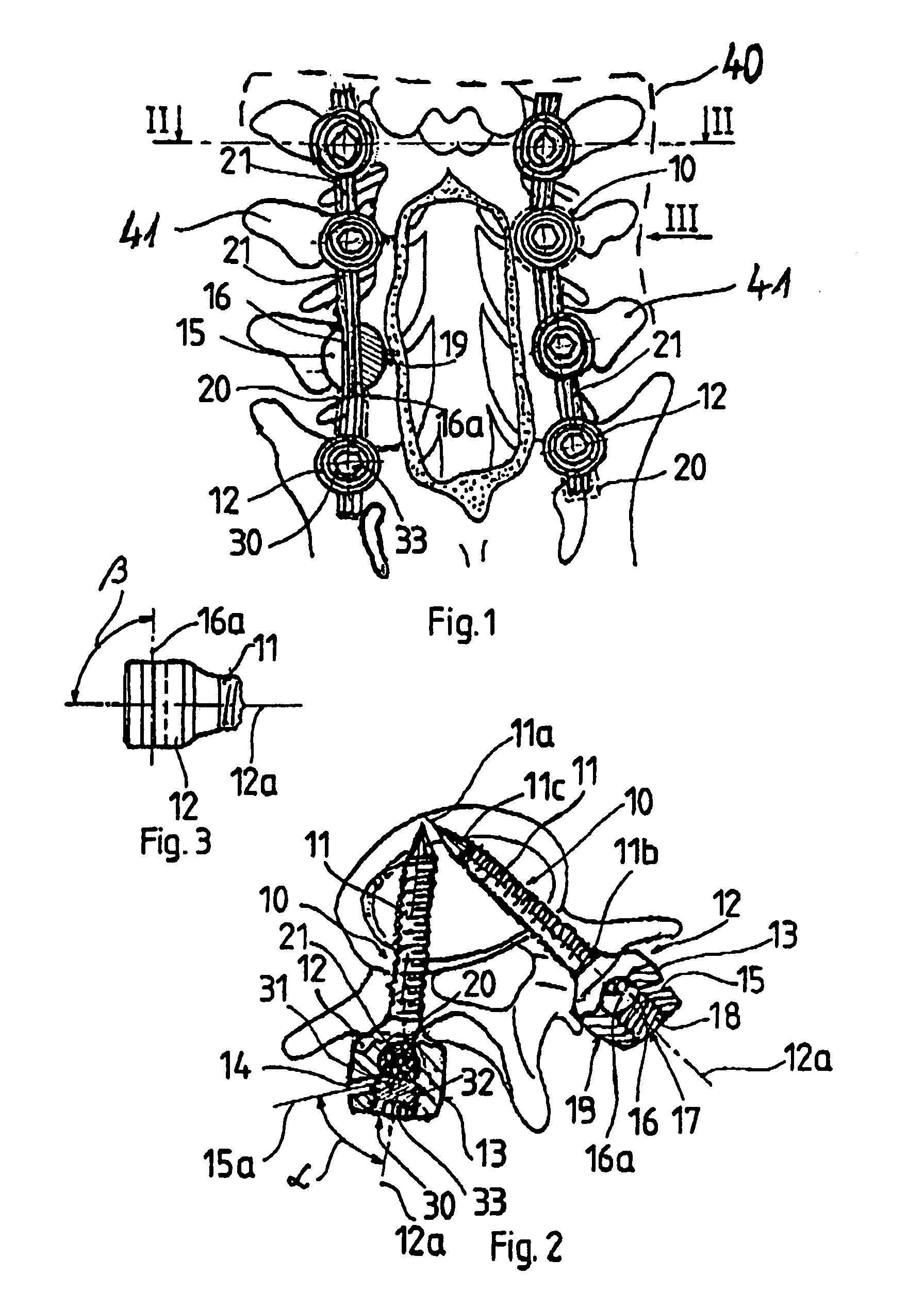
[0035]FIG. 1 shows the surgical instrument set according to the invention built into the vertebrae 41 of the spinal column 40 in an assembled state. It can be easily seen that each one of the supporting elements 10 is fixed into a separate vertebra 41 so that the head parts 12 protrude out of the vertebrae 41. The supporting elements 10 are positioned so that the axes of symmetry 16a of the lead-through seats 16 in the head parts 12 fall in the longitudinal direction of the spinal column 40. The elemental connection strands 21 are in the lead-through seats 16 of the head parts 12 of the supporting elements 10, with elemental connection strands 21 together forming the connecting unit 20. The connecting unit 20 assembled from the elemental connection strands 21 is held in the lead-through seats 16 of the head parts 12 by the tightening bodies 31 (see FIG. 2) of the fixating devices 30. The tightening bodies 31 of the fixating devices 30 have a connector piece 33, with the help of whic...


PUM


Abstract

A set of surgical instruments for the fusion of vertebrae contains supporting elements that have a threaded stem that can be screwed into the vertebra and a head part positioned at the outer end of the threaded stem. A connection unit is fitted between the supporting elements and a fixating device serving to brace together the supporting elements and the connection unit, and the head part of the supporting element has an accepting opening suitable for joining the connecting unit. The accepting opening is formed by the unification of an introductory cleft running from the outer surface of the head part and penetrating into the head part, and a lead-through seat that forms the continuation of the introductory cleft, is worked into the head part and bells out from there. The head part has a fusion opening that has a first connection piece and ends in the lead-through seat, and the fixating device has a tightening body that is positioned in the fusion opening so that it may move. A second connecting piece operates in unison with the first connecting piece, and the connecting unit is assembled from the group of the elemental connection strands penetrating the introductory cleft of the head part.

Description

TECHNICAL FIELD[0001]The subject of the invention relates to a set of surgical instruments designed for fixating or fusing spinal vertebrae. The instruments include supporting elements having a threaded rod or stem that can be screwed into the vertebra and a head part or unit positioned at the top or outer end of the threaded rod or stem, a connecting unit that is fitted between the supporting elements, and a fixating device serving to brace together the supporting elements and the connecting unit. The head part or unit of the supporting element has an accepting opening suitable for joining the connecting unit. The accepting opening is formed by the unification of the introductory cleft running from the outer surface of the head part or unit and penetrating into the head part or unit. A lead-through seat forms the continuation of the introductory cleft, is worked into the head part or unit, and bells out from there. Furthermore, the head part or unit has a fusion opening that has a ...

Claims


Application Information

Patent Timeline
Patent Type & Authority Patents(United States)
IPC IPC(8): A61B17/56A61F2/30
CPCA61B17/7002A61B17/7034
Inventor FARKAS, JOZSEFVARGA, PETER PAL
Owner SANATMETAL
Learn More