Process for steam cracking heavy hydrocarbon feedstocks

a hydrocarbon feedstock and steam cracking technology, applied in the cracking process of hydrocarbon oil, thermal non-catalytic cracking, organic chemistry, etc., can solve the problems of crude oil, coking problems, contamination of naphthas,

Inactive Publication Date: 2006-11-21
EXXONMOBIL CHEM PAT INC
View PDF68 Cites 185 Cited by
  • Summary
  • Abstract
  • Description
  • Claims
  • Application Information

AI Technical Summary

Benefits of technology

[0024](e) controlling the temperature of the hot mixture stream and controlling the ratio of steam to hydrocarbon by varying the flow rate of the water and the flow rate of the primary dilution steam;

Problems solved by technology

However, steam cracking economics sometimes favor cracking lower cost heavy feedstocks such as, by way of non-limiting examples, crude oil and atmospheric resid.
Additionally, during transport some naphthas are contaminated with heavy crude oil containing non-volatile components.
Conventional pyrolysis furnaces do not have the flexibility to process resids, crudes, or many resid or crude contaminated gas oils or naphthas which are contaminated with non-volatile components hydrocarbons.
Otherwise, heavy, coke-forming non-volatile components in the vapor are carried into the furnace causing coking problems.
Otherwise, valuable lighter fractions of the hydrocarbon feedstock could be lost in the liquid hydrocarbon bottoms or heavy, coke-forming components could be vaporized and carried as overhead into the furnace causing coking problems.
The control of the ratio of vapor to liquid leaving flash has been found to be difficult because many variables are involved.
With all these variables, it is difficult to control a constant ratio of vapor to liquid leaving the flash.

Method used


Image

  • Process for steam cracking heavy hydrocarbon feedstocks
  • Process for steam cracking heavy hydrocarbon feedstocks

Examples


example 1

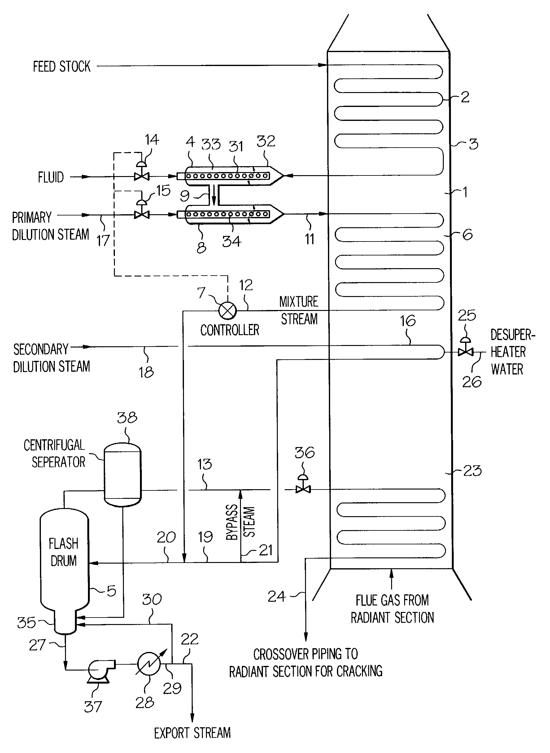
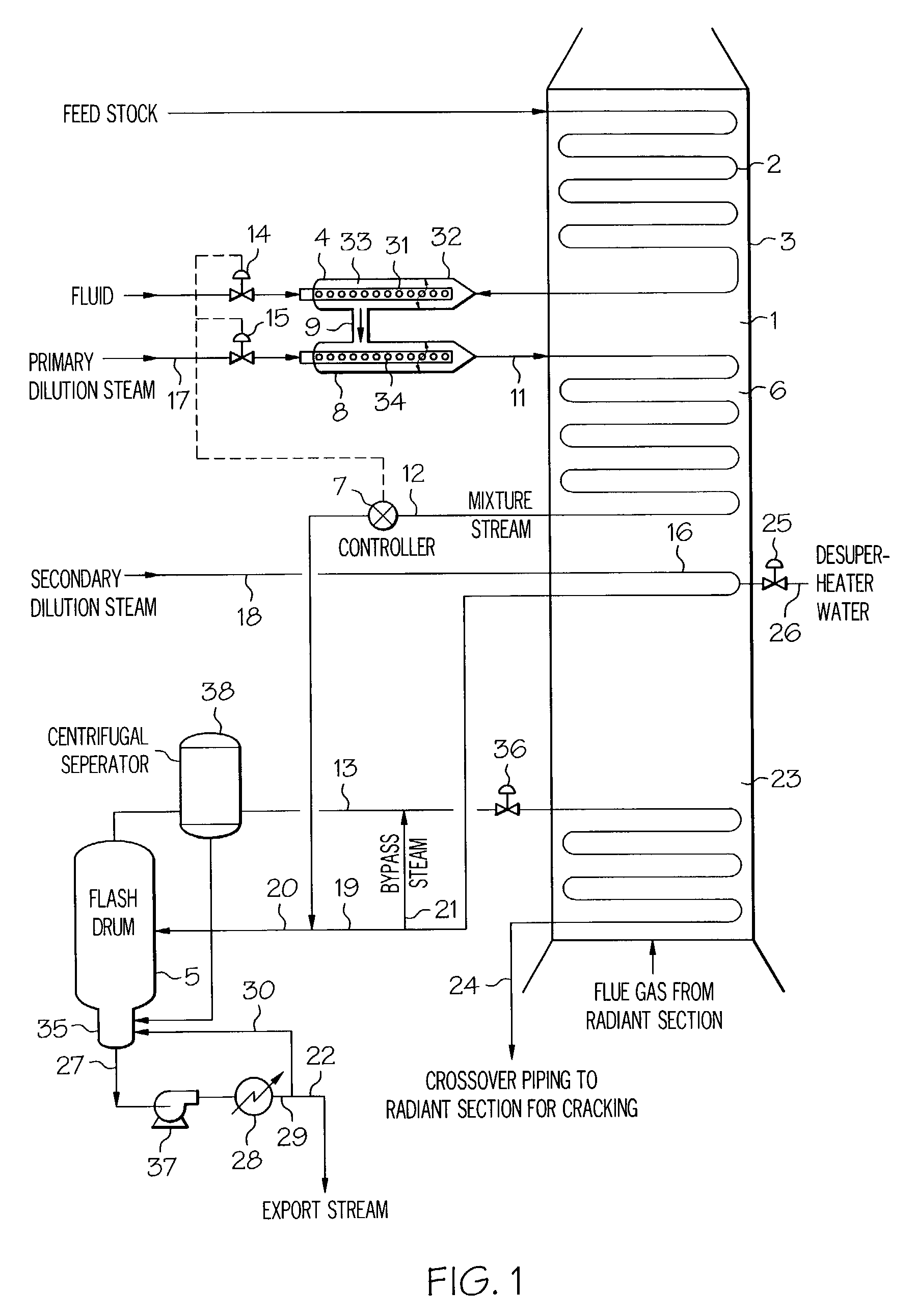
[0066]Engineering calculations which simulate processing atmospheric pipestill bottoms (APS) and crude oil by this invention have been conducted. The attached Table 1 summarizes the simulation results for cracking Tapis APS bottoms and Tapis crude oil in a commercial size furnace with a flash drum. The very light components in crudes act like steam reducing the partial pressure of the heavy components. Hence, at a nominal 950° F. (510° C.) cut point, the flash drum can operate 100° F. (50° C.) lower temperature than for atmospheric resids.

[0067]

TABLE 1Summary of Atmospheric Pipestill (APS) Bottomsand Crude Oil Flash Drum SimulationsAPSFIG. 1BottomsCrudeRef. #Convection feed rate, klb / hr (t / h)126(57)100(45)n / a950° F. minus (510° C.), wt %7093n / aTemperature before sparger, ° F.400(205)352(178)4(° C.)Sparger water rate, klb / h (t / h)12(5)43(20)14Primary dilution steam rate,18(8)8(4)17klb / h (t / h)Secondary dilution steam rate,17(8)19(9)18klb / h (t / h)Desuperheater water rate,6(3)6(3)26klb / h ...

example 2

[0068]Table 2 summarizes the simulated performance of the flash for residue admixed with two concentrations of C4's. At a given flash temperature, pressure and steam rate, each percent of C4's admixed with the residue increases the residue vaporized in the flash by ¼%. Therefore, the addition of C4's to feed will result in more hydrocarbon from the residue being vaporized.

[0069]

TABLE 2C4's / Residue Admixture Flash PerformancePureMix 1:Mix 2:ResidueResidue + C4'sResidue + C4'sWt % residue in convection1009489feedWt % C4's in convection0611feedBubble point, ° F.991327244@ 112 psigWt % of residue vaporized65.0%68.2%70.8%in flashOverall wt % vaporized65.0%69.9%74.0%in flashTemperature, ° F.819819819Wt % of residue vaporized70.0%72.8%75.1%in flashOverall wt% vaporized in70.0%74.3%77.8%flashTemperature, ° F.835835835Wt % of residue vaporized75.0%77.4%79.4%in flashOverall wt % vaporized75.0%78.6%81.7%in flashTemperature, ° F.855855855


PUM

PropertyMeasurementUnit
temperatureaaaaaaaaaa
boiling pointaaaaaaaaaa

Abstract

A process for feeding or cracking heavy hydrocarbon feedstock containing non-volatile hydrocarbons comprising: heating the heavy hydrocarbon feedstock, mixing the heavy hydrocarbon feedstock with a fluid and / or a primary dilution steam stream to form a mixture, flashing the mixture to form a vapor phase and a liquid phase, and varying the amount of the fluid and / or the primary dilution steam stream mixed with the heavy hydrocarbon feedstock in accordance with at least one selected operating parameter of the process, such as the temperature of the flash stream before entering the flash drum.

Description

BACKGROUND OF THE INVENTION[0001]1. Field of the Invention[0002]The present invention relates to the cracking of hydrocarbons that contain relatively non-volatile hydrocarbons and other contaminants.[0003]2. Description of Background and Related Art[0004]Steam cracking has long been used to crack various hydrocarbon feedstocks into olefins. Conventional steam cracking utilizes a pyrolysis furnace which has two main sections: a convection section and a radiant section. The hydrocarbon feedstock typically enters the convection section of the furnace as a liquid (except for light feedstocks which enter as a vapor) wherein it is typically heated and vaporized by indirect contact with hot flue gas from the radiant section and by direct contact with steam. The vaporized feedstock and steam mixture is then introduced into the radiant section where the cracking takes place. The resulting products including olefins leave the pyrolysis furnace for further downstream processing, such as quench...

Claims


Application Information

Patent Timeline
Patent Type & Authority Patents(United States)
IPC IPC(8): C10G9/36C10G9/00
CPCC10G9/00C10G9/36
Inventor STELL, RICHARD C.DINICOLANTONIO, ARTHUR R.FRYE, JAMES MITCHELLSPICER, DAVID B.MCCOY, JAMES N.STRACK, ROBERT DAVID
Owner EXXONMOBIL CHEM PAT INC
Why Eureka
Try Eureka