
Method and circuit for trimming a current source in a package

a current source and package technology, applied in the direction of dc-amplifiers with dc-coupled stages, differential amplifiers, semiconductor devices/discharge tubes, etc., can solve the problems of reducing the trimming technique accuracy, requiring an additional pin, and reducing the desirable size of modern micro-sized packaged devices. , to achieve the effect of simplifying the trimming technique, improving accuracy, and facilitating the trimming of the current sour

Active Publication Date: 2006-11-21
TEXAS INSTR INC
View PDF5 Cites 59 Cited by
  • Summary
  • Abstract
  • Description
  • Claims
  • Application Information

AI Technical Summary

Benefits of technology

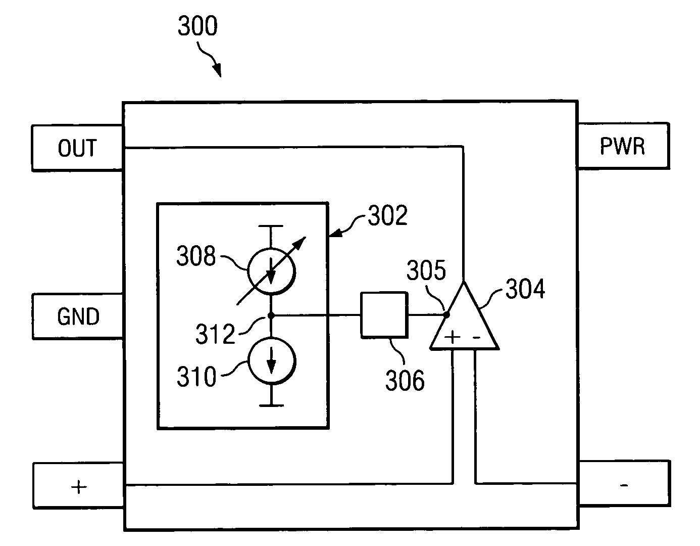
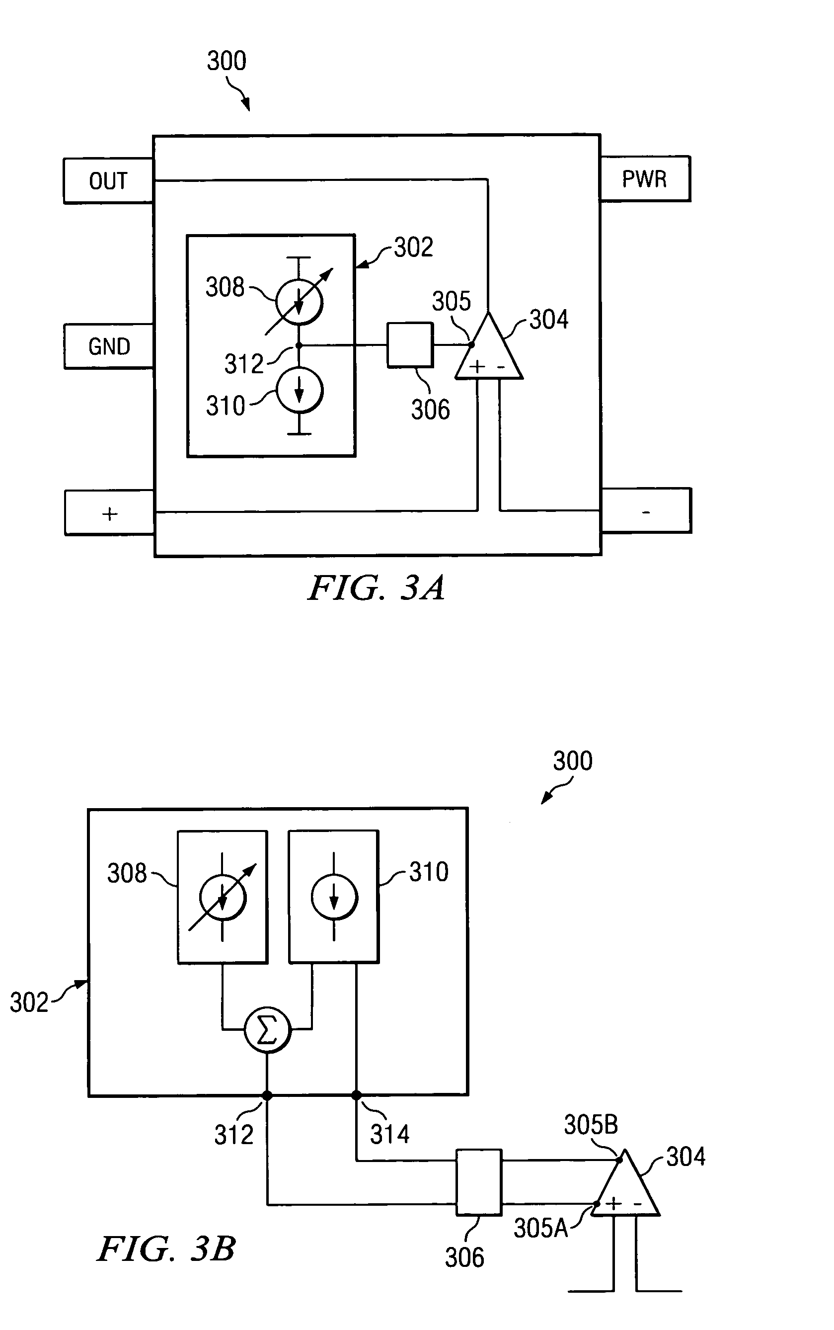
The present invention provides a method and circuit for trimming a current source in a packaged device without the need for additional pins or dual function pins. This improves accuracy and simplifies trimming techniques. The packaged device includes a current trimming network and a coupling circuit that can connect or disconnect the current source to a monitor input of the device. The method involves adjusting the magnitude of the current source to a desired proportion of a reference current source, and iteratively adjusting the current source until the desired proportion is achieved. The technical effect is improved accuracy and simplified trimming techniques in packaged devices.

Problems solved by technology

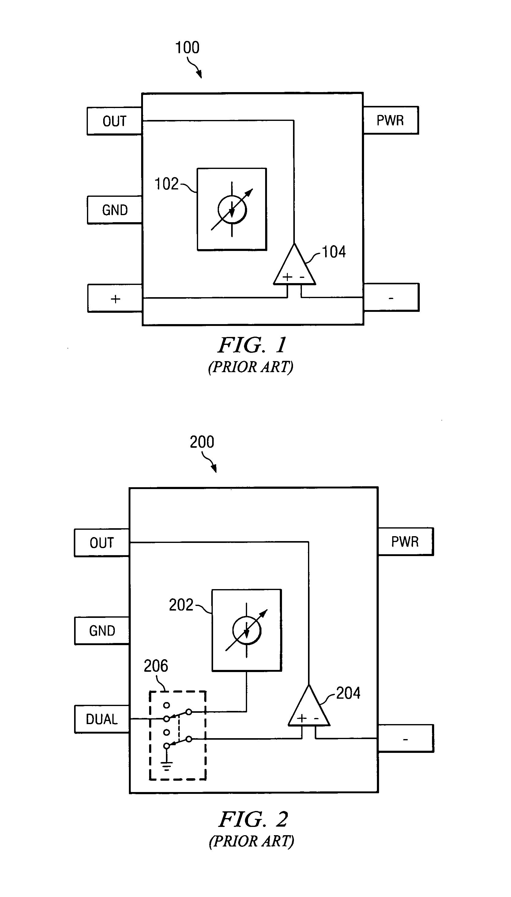
Requiring an additional pin is less desirable in modern micro-sized packaged devices.
While such a technique is conducted without the need for an extra package pin, the technique is susceptible to measurement errors.
As a result, an error is added to the measurements resulting in a reduced accuracy in the trimming technique.

Method used


Image

  • Method and circuit for trimming a current source in a package
  • Method and circuit for trimming a current source in a package
  • Method and circuit for trimming a current source in a package

Examples


Embodiment Construction

[0018]The present invention may be described herein in terms of various functional components and various processing steps. It should be appreciated that such functional components may be realized by any number of hardware or structural components configured to perform the specified functions. For example, the present invention may employ various integrated components, e.g., buffers, voltage and current references, memory components and the like, comprised of various electrical devices, e.g., resistors, transistors, capacitors, diodes or other devices, whose values may be suitably configured for various intended purposes. In addition, the present invention may be practiced in any amplifier, reference, sensor, or other electronics based application. However for purposes of illustration only, exemplary embodiments of the present invention are described herein in connection with an op amp circuit.

[0019]Further, it should be noted that while various components may be suitably coupled or...


PUM


Abstract

A method and circuit for trimming a current source packaged with a device can facilitate trimming of the current source without the need for additional pins or dual function pins, resulting in improved accuracy and / or simplified trimming techniques. An exemplary packaged device is configured with a trimming circuit comprising a current trimming network and a coupling circuit. An exemplary packaged device can comprise any op amp, current or voltage reference, and / or sensor device, and is configured with one or more monitor inputs. An exemplary current trimming network comprises a variable current source and a reference current source, wherein a magnitude of the variable current source can be compared to the magnitude of the reference current source. An exemplary coupling circuit is coupled between the current trimming network and the device and is configured for enabling and disabling connection of an output of the current trimming network and a monitor input of the device. During an exemplary trimming method, the variable current source is configured with a magnitude adjusted to a desired proportion of a magnitude of the reference current source, with the current trimming network configured to produce a current proportional to the difference, sum, or product of the first and second current sources.

Description

FIELD OF INVENTION[0001]The present invention relates to the trimming of a device. More particularly, the present invention relates to a method and circuit for trimming a current source within a package with a device, such as operational amplifiers, reference, temperature sensor and other like devices.BACKGROUND OF THE INVENTION[0002]The demand for higher performance, amplifier, reference and sensor devices for use in communication, instrumentation and processing applications continues to increase. For example, designers and manufactures of such applications are requiring for the accuracy of the components and devices, such as operational amplifiers (“op amps”), current and voltage references, and temperature sensors and the like, to be continually improved to meet the higher performance requirements of a myriad of emerging audio, video, imaging and wireless applications.[0003]Op amps, references, sensors and other similar types of devices typically are varied and adjusted through t...

Claims


Application Information

Patent Timeline
Patent Type & Authority Patents(United States)
IPC IPC(8): H03F3/45
CPCH03F3/45183H03F3/45475H03F2203/45366
Inventor SANCHEZ, STEPHEN J.HISER, DARYL
Owner TEXAS INSTR INC
Learn More