Field coil assembly for an electromagnetic clutch for a compressor

a compressor and electromagnetic technology, applied in the direction of mechanical actuators, magnets, magnetic bodies, etc., can solve the problems of reducing assembly efficiency, corroding the electromagnetic coil body b>2/b>, and too complicated manufacturing processes

Active Publication Date: 2006-11-21
HANON SYST
View PDF15 Cites 24 Cited by
  • Summary
  • Abstract
  • Description
  • Claims
  • Application Information

AI Technical Summary

Benefits of technology

[0027]Accordingly, the present invention has been made to solve the above-mentioned problems occurring in the prior art, and it is an object of the present invention to provide a field coil assembly of an electromagnetic clutch for a compressor, in which a coil wire of an electromagnetic coil body exposed to a protrusion of a bobbin is electrically connected with a compressing portion of a coil wire formed at one side end portion of terminals mounted inside a sleeve, and the terminals and the electromagnetic coil body are molded with the resin, thereby preventing permeation of foreign matters from the outside, preventing disconnection of the coil wires due to vibration, and simplifying a manufacturing process.
[0028]To accomplish the above objects, according to the present invention, there is provided a field coil assembly of an electromagnetic clutch for a compressor including: an electromagnetic coil body having an electromagnetic coil wound thereon in a ring type and a coil wire drawn out from an end portion thereof; a bobbin accommodating the electromagnetic coil body therein and having a protrusion formed on a side of the upper portion thereof and a communicating passage formed on the protrusion for allowing resin to flow through the communicating passage; a core ring having a throughhole formed on a side of the upper portion thereof for exposing the protrusion and the coil wire to the outside the therethrough and an opened part formed on the lower portion thereof for accommodating the bobbin therein; and a sleeve having a coil wire compressing portion formed at one side end portion thereof and electrically connected with the coil wire, terminals formed at the other side end portion thereof and connected with an external power supply, and a body integrally formed in such a way as to surround the terminals, the sleeve being temporarily fixed on the core ring, whereby the electromagnetic coil body is molded and fixed inside the core ring by filling the opened part of the core ring with the resin, and the coil wire and the coil wire compressing portion are molded with some of the resin flowing through the communicating passage of the bobbin so as to improve sealing efficiency.
[0033]The field coil assembly according to the present invention further includes a cover for protecting the coil wire and the terminals from the outside.

Problems solved by technology

However, the field coil assembly 2 of the hard shell type has a disadvantage in that the electromagnetic coil body 2 is corroded due to permeation of moisture through a fine gap formed by the cover 2d and the core ring 2c.
However, the field coil assembly of the epoxy type has several disadvantages in that it takes much time to install the diode 7 and the resistor 8, in that a manufacturing process is too complicated, and in that assembly efficiency is lowered.
However, the prior art also has several disadvantages in that an error rate rises since the connector of a complex shape is integrally injection-molded, and in that the coil wire and the terminals may be transformed by a high injection pressure since even the connector body is integrally injection-molded.
Additionally, the prior art has other disadvantages in that an assembly process and an injection process of the coil wire and the terminals are very complicated, and in that productivity is lowered since it is difficult to install a surge prevention element.

Method used


Image

  • Field coil assembly for an electromagnetic clutch for a compressor
  • Field coil assembly for an electromagnetic clutch for a compressor
  • Field coil assembly for an electromagnetic clutch for a compressor

Examples


Embodiment Construction

[0045]Reference will be now made in detail to the preferred embodiment of the present invention with reference to the attached drawings.

[0046]FIGS. 4 to 8 are views showing a field coil assembly according to a first preferred embodiment of the present invention.

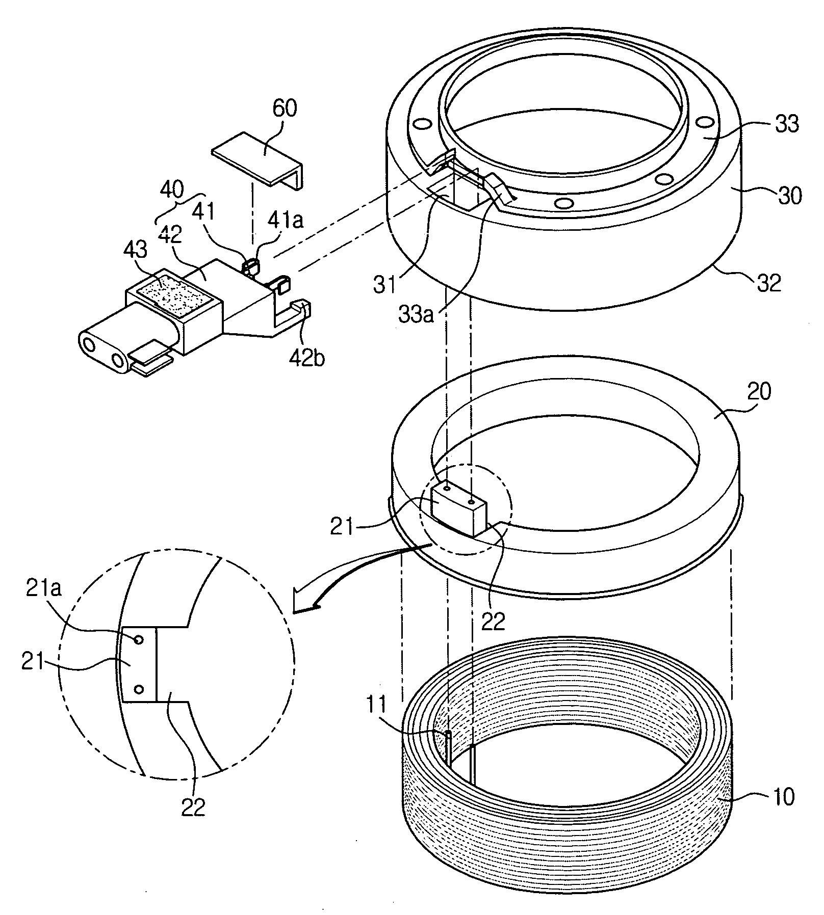
[0047]As shown in the drawings, the field coil assembly includes an electromagnetic coil body 10, a bobbin 20, a core ring 30, and a sleeve 40.

[0048]The electromagnetic coil body 10 is in the form of a ring, and has an electromagnetic coil wounded thereon and a coil wire 11 drawn out from both end portions thereof.

[0049]The bobbin 20 accommodates the electromagnetic coil body 10 therein, and includes a protrusion 21 formed at a side of the upper portion thereof, coil holes 21a formed on the protrusion 21, and a communicating passage 22 formed nearly to the protrusion 21 for allowing flow of resin.

[0050]It is preferable that the coil wire 11 is exposed upwardly through the coil hole 21a of the protrusion 21.

[0051]The core ring...


PUM

PropertyMeasurementUnit
magnetic fieldaaaaaaaaaa
magnetic forceaaaaaaaaaa
frictionaaaaaaaaaa

Abstract

The present invention relates to a field coil assembly of an electromagnetic clutch for a compressor, in which a coil wire of an electromagnetic coil body exposed to a protrusion of a bobbin is electrically connected with a compressing portion of a coil wire formed at one side end portion of terminals mounted inside a sleeve, and the terminals and the electromagnetic coil body are molded with the resin, thereby preventing permeation of foreign matters from the outside, preventing disconnection of the coil wires due to vibration, and simplifying a manufacturing process.

Description

BACKGROUND OF THE INVENTION[0001]This application claims priority from Korean Patent Application No. 2004-80593 filed Oct. 8, 2004 incorporated herewith by reference in its entirety.[0002]1. Field of the Invention[0003]The present invention relates to a field coil assembly of an electromagnetic clutch for a compressor, and more particularly, to a field coil assembly of an electromagnetic clutch for a compressor, in which a coil wire of an electromagnetic coil body exposed to a protrusion of a bobbin is electrically connected with a compressing portion of a coil wire formed at one side end portion of terminals mounted inside a sleeve, and the terminals and the electromagnetic coil body are molded with the resin, thereby preventing permeation of foreign matters from the outside, preventing disconnection of the coil wires due to vibration, and simplifying a manufacturing process.[0004]2. Background Art[0005]In general, a field coil assembly of an electromagnetic clutch for a compressor...

Claims


Application Information

Patent Timeline
Patent Type & Authority Patents(United States)
IPC IPC(8): F16D27/112H01F27/30H01F5/04
CPCF16D27/112F16D27/14H01F5/04H01F7/06H01F7/08H01F7/128F16D2027/001H01F5/06H01F27/022H01F27/04H01F2007/062F16D27/10
Inventor CHUNG, SUKJAE
Owner HANON SYST
Why Eureka
Try Eureka