Information recording apparatus and information recording method

a technology of information recording apparatus and information recording method, which is applied in the field of recording information technology, can solve the problems of difficult control of the recording pulse driving the recording laser, inability to precisely control the heat quantity given to the optical disk by laser irradiation, and inability to control the heat quantity of the optical disk

Active Publication Date: 2006-11-21
PIONEER CORP
View PDF8 Cites 18 Cited by
  • Summary
  • Abstract
  • Description
  • Claims
  • Application Information

AI Technical Summary

Benefits of technology

[0025]The space period may further include an off period which is located immediately after the intermediate bias period and whose amplitude level is zero. By this feature, the recording surface of the recording medium can be quenched because a laser beam level falls down to zero immediately after the intermediate bias period, which enables the influence of the thermal interference on the following recording mark to ...

Problems solved by technology

However, there is such a problem that control of the recording pulse driving the recording laser becomes difficult because a clock becomes faster in the case of high-speed recording.
This causes the control of heat quantity applied to the optical disk by the laser irradiation to be difficul...

Method used


Image

  • Information recording apparatus and information recording method
  • Information recording apparatus and information recording method
  • Information recording apparatus and information recording method

Examples


first embodiment

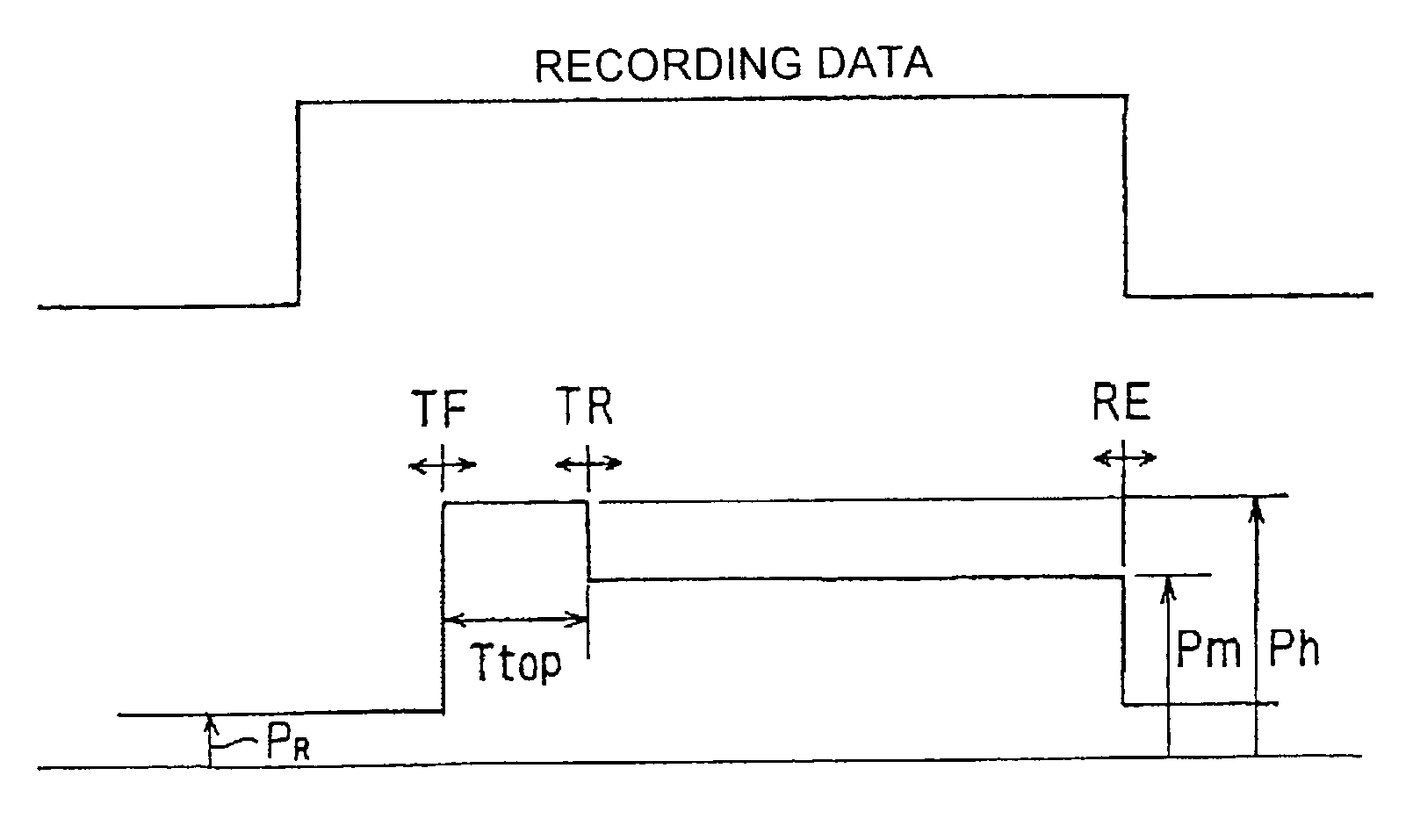
[0078]FIG. 5 shows a recording pulse waveform according to the write strategy of the invention. As shown in FIG. 5, the recording pulse waveform according to the write strategy of the embodiment includes three parts, i.e., a top pulse 40, an intermediate bias portion 41 and a last pulse 42. The recording pulse waveform is maintained at the level of the read power PR at the portions other than those three portions.

[0079]In the write strategy of the invention, two values of the write powers are used. The top pulse 40 and the last pulse 42 have the first write power Ph, and the intermediate bias portion 41 has the second write power Pm. The second write power Pm is set to be higher than the read power PR and lower than the first write power Ph.

[0080]The top pulse 40 has a role of preheating a recording surface of the optical disk for recording a mark. A time width of the intermediate bias portion 41 varies correspondingly to length of the mark to be recorded. The last pulse 42 has main...

second embodiment

[0127]FIGS. 16A to 16C show the values of the jitter, the modulation and the asymmetry by solid lines, respectively, when the value of the first write power Ph is varied for the recording pulse waveform (Type 2) according to the In each case, the write power ratio is fixed at a value of about 150% obtained from the above-described discussion. Variations in the case where the write power ratio is not fixed is shown by dotted lines.

[0128]Similar tendency as FIGS. 15A to 15C is found in this case. As shown by solid lines in FIG. 16A, even though the first write power Ph is increased, the jitter does not become so bad. As shown in FIG. 15B, since the second write power Pm is increased when the first write power Ph is increased, the modulation is increased. As shown in FIG. 15C, the asymmetry has relation in almost direct proportion to the first write power Ph, and it is desirable that the first write power Ph is near 21 mW, where the value of the asymmetry becomes almost zero.

[0129]Wit...


PUM


Abstract

The information recording apparatus irradiates a laser beam on a recording medium such as an optical disk and forms a recording mark corresponding to a recording signal to record information. A recording pulse signal includes a mark period irradiating the laser beam for forming the recording mark and a space period in which the recording mark is not formed. The mark period has a top pulse period and an intermediate bias period following the top pulse period. The mark period constituted by the top pulse period and the intermediate bias period does not have a continuous part of a plurality of pulses having a small pulse width unlike a pulse train, so that the correct recording mark can be stably formed on the recording medium without an inadequate deformation of a recording pulse shape, even in the case of a high speed recording.

Description

FIELD OF THE INVENTION[0001]The present invention relates to technique of recording information on an optical disk by utilizing a laser beam.DESCRIPTION OF RELATED ART[0002]On a recordable or re-recordable optical disk such as DVD-R a (DVD-Recordable) and a DVD-RW (DVD-Re-recordable), a laser beam is irradiated on a recording surface of the optical disk to record information. Increase in temperature of a part on the recording surface of the optical disk irradiated by the laser beam causes a change of state of an optical recording medium constituting the optical disk, which causes a recording mark to be formed on the recording surface.[0003]The laser beam is modulated by a recording pulse having a time width corresponding to information to be recorded so that a laser pulse of a length corresponding to a signal to be recorded is generated, and the laser pulse is irradiated on the optical disk. This permits the recording mark of a length corresponding to the information to be recorded ...

Claims


Application Information

Patent Timeline
IPC IPC(8): G11B7/00G11B7/0045G11B7/006G11B7/1263
CPCG11B7/0062G11B7/00456G11B7/0045G11B7/1263
Inventor SHIROTA, AKIRAHORIKAWA, KUNIHIKOMURAMATSU, EIJITANIGUCHI, SHOJI
Owner PIONEER CORP
Why Eureka
Try Eureka