Adjustment device for a fine machining tool

a fine machining tool and adjustment device technology, applied in the direction of metal-working hand tools, sleeves/socket joints, boring/drilling components, etc., can solve the problem that the fine adjustment of the position of the cutter which is desirable for fine machining tools cannot be achieved in this manner

Active Publication Date: 2006-11-28
GUHRING JORG
View PDF17 Cites 16 Cited by
  • Summary
  • Abstract
  • Description
  • Claims
  • Application Information

AI Technical Summary

Benefits of technology

[0011]The object of the present invention is thus to create an adjustment device for a fine machining tool which can be used to set the positio...

Problems solved by technology

However, the problem that arises is that the work is subject to extremely small diameter tolerances, i.e., the position of the cutting edge(s) must be set precisely in the radial direction.
Using the known chucking and restraining ...

Method used


Image

  • Adjustment device for a fine machining tool
  • Adjustment device for a fine machining tool
  • Adjustment device for a fine machining tool

Examples


Embodiment Construction

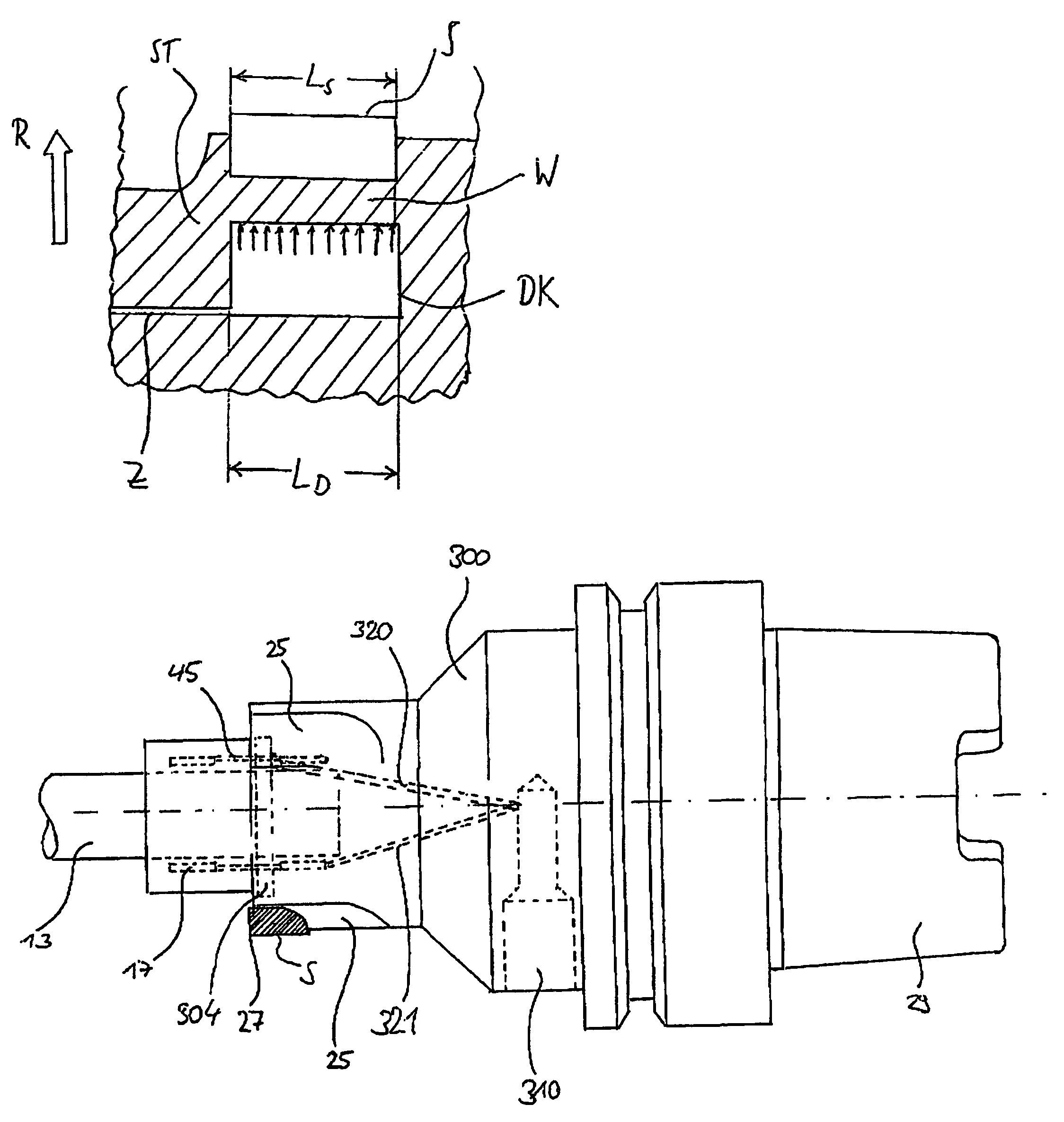
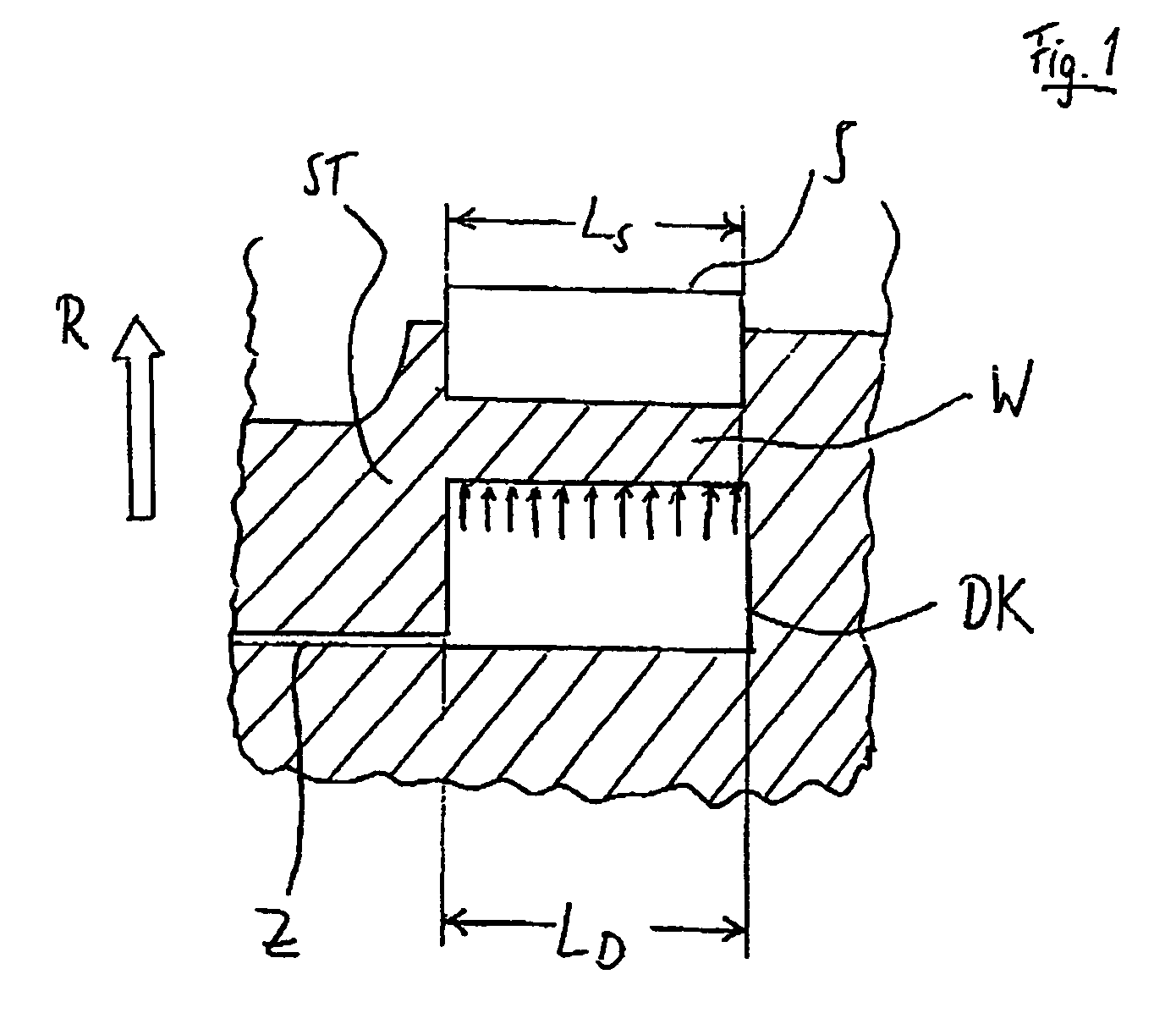
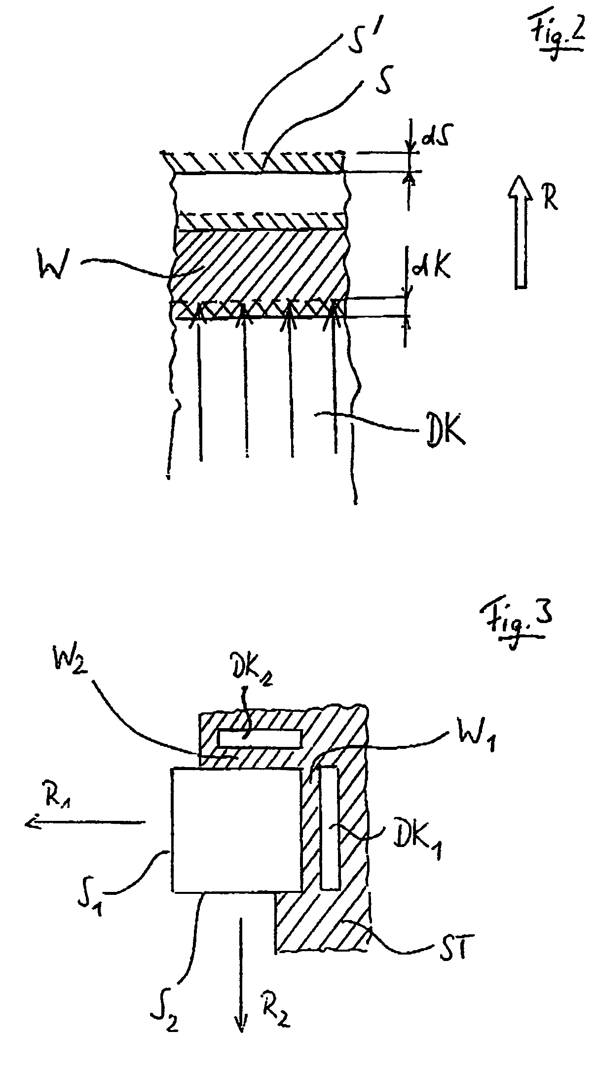
[0055]Reference is made initially to FIGS. 1 and 2, and the principle of operation of the adjustment device according to the invention will be explained. A pressure chamber DK is arranged below a cutter S which pressure chamber DK is filled with a pressure transfer means and has a pressure applied to it via a line Z. Between the cutter S on an exchangeable cutting insert and the pressure chamber DK, there is an outer wall W of the pressure chamber DK having a small thickness while the pressure chamber is otherwise enclosed with fill material. As is shown by the arrows in the pressure chamber DK, the outer wall W of the pressure chamber DK experiences upon application of an external pressure a two-dimensional load. If this load exceeds a certain value, the wall W is deformed in direction R. Since the length LD of the pressure chamber corresponds to the length LS of the cutter, there arises over the cutter length LS in many parts an extension of the pressure chamber to the outside, i....


PUM

PropertyMeasurementUnit
Lengthaaaaaaaaaa
Pressureaaaaaaaaaa
Sizeaaaaaaaaaa

Abstract

An adjustment device for adjusting the position of at least one cutter of a fine machining tool, particularly a reamer, with respect to a cutter support (ST) is described. To allow the cutter to be adjusted as precisely as possible, the cutter support (ST) borders at least one pressure chamber (DK) which is arranged in the adjustment direction of the cutter (S) with a displacement with respect to it and which is filled with a pressure medium which can be placed under pressure using a pressure generation device. Between the cutter (S) and the pressure chamber (DK), a cutter support wall (W) remains which is elastically deformable upon application of pressure by the pressure transfer means to adjust the cutter position.

Description

BACKGROUND OF THE INVENTION[0001]1. Field of the Invention[0002]The invention relates to an adjustment device for adjusting the position of at least one cutter of a fine machining tool, particularly a reamer, with respect to a cutter support, as well as to a corresponding fine machining tool.[0003]2. Description of Related Art[0004]In fine machining tools of this sort, one of the accuracy requirements is that the cutting edges must move in an orbit which is well centered on the rotational axis of the tool. Various solutions to solving this problem are known:[0005]To enable precisely centered restraint of a tool shank, e.g., a drill shank or a burr shaft, hydraulic expansion chucks are known, for example, from DE-GM 94 11 260 or DE 27 00 934 A1 in which a toroidal chamber in the clamping chuck element is bordered radially inwards by an expansion bush which elastically deforms inwards in the radial direction upon placement of a hydraulic pressure in the toroidal chamber and which thus...

Claims


Application Information

Patent Timeline
IPC IPC(8): B23C5/00B23B29/034B23D77/04B23B31/30
CPCB23B29/03421B23B31/305B23D77/04B23B29/03457Y10T279/1216B23B2270/025B23B2270/24B23D2277/085Y10T408/8595Y10T409/309408Y10T279/1029Y10T408/85Y10T279/1233Y10T279/29Y10T409/30952Y10T408/62Y10T408/85843
Inventor BROGHAMMER, HANS-PETEREHRLER, ROLF
Owner GUHRING JORG
Why Eureka
Try Eureka