Variable depth drill with self-centering sleeve

a drill and self-centering technology, applied in bone drill guides, medical science, surgery, etc., can solve the problems of nerve root compression, change in bones, discs, joints, ligaments of the spine, and difficulty in implantation so as to facilitate the placement of spinal fixation plates and precise control of the entry angl

Inactive Publication Date: 2006-11-28
DEPUY SPINE INC (US)
View PDF45 Cites 63 Cited by
  • Summary
  • Abstract
  • Description
  • Claims
  • Application Information

AI Technical Summary

Benefits of technology

[0006]The present invention generally provides a surgical drill assembly that can be used to facilitate the placement of a spinal fixation plate along a patient's spinal column. In general, the surgical drill assembly includes an elongate shaft having a proximal end that is adapted to mate to a driver mechanism, and a distal end having a bone preparation element formed thereon. An elongate, hollow sleeve is coupled to, but slidably disposed around at least a portion of the elongate shaft. In an exemplary embodiment, the hollow sleeve includes a stepped region that is positioned between proximal and distal portions such that the distal portion of the hollow sleeve has an outer diameter that is less than an outer diameter of the stepped region. In use, the elongate, hollow sleeve is effective to longitudinally align the elongate shaft therein during a surgical procedure. More particularly, the distal portion of the hollow sleeve can be disposed within a lumen in a drill guide, and the stepped region will abut the drill guide. As a result, the sleeve aligns the bone preparation element with the lumen in the guide member, thus aligning the bone preparation element with a bore in a spinal fixation plate that is coupled to the guide member. This will provide the user with precise control over the entry angle of the bone preparation element into bone.
[0007]In one embodiment, the elongate shaft can be biased with respect to the elongate, hollow sleeve to prevent the shaft from interfering with insertion of the sleeve into a lumen in a guide device. The biasing force is preferably adapted such that a force is necessary to overcome the biasing force to cause the elongate shaft to move in a distal direction with respect to the elongate, hollow sleeve. The biasing force can be created by a biasing member, such as a spring, that is disposed within at least a portion of the elongate, hollow sleeve to bias the elongate shaft in a proximal direction such that a force greater than a biasing force created by the biasing member is required to move the elongate shaft in a distal direction with respect to the elongate, hollow sleeve. The biasing member preferably acts on a flange that is formed around the elongate shaft, such that distal movement of the elongate shaft will cause the flange to abut and compress the biasing member. The device can also optionally include a pin extending through a sidewall of the hollow sleeve that is adapted to abut the flange to prevent removal of the elongate shaft from within the hollow sleeve. In an alternative embodiment, an engagement member, such as a ball and detent, can be formed on and disposed between the elongate shaft and the hollow sleeve such that the engagement member is effective to maintain the hollow sleeve in a predetermined position with respect to the elongate shaft.

Problems solved by technology

Advancing age, as well as injury, can lead to changes in the bones, discs, joints, and ligaments of the spine, producing pain from nerve root compression.
Implantation of a spinal fixation plate can be difficult, as each plate must be properly aligned with the vertebral bodies, and holes for receiving the bone screws must be drilled into the vertebrae at precise angles.
Such a procedure can be difficult, however, as the surgeon is required to securely and rigidly hold the bone plate against the vertebrae, obtain proper alignment, drill, tap, and finally set the bone screws.
Some secondary instruments have been provided to center the drill bit within the drill guide lumen, however the use of additional devices is undesirable as it complicates the surgical procedure.

Method used


Image

  • Variable depth drill with self-centering sleeve
  • Variable depth drill with self-centering sleeve
  • Variable depth drill with self-centering sleeve

Examples


Embodiment Construction

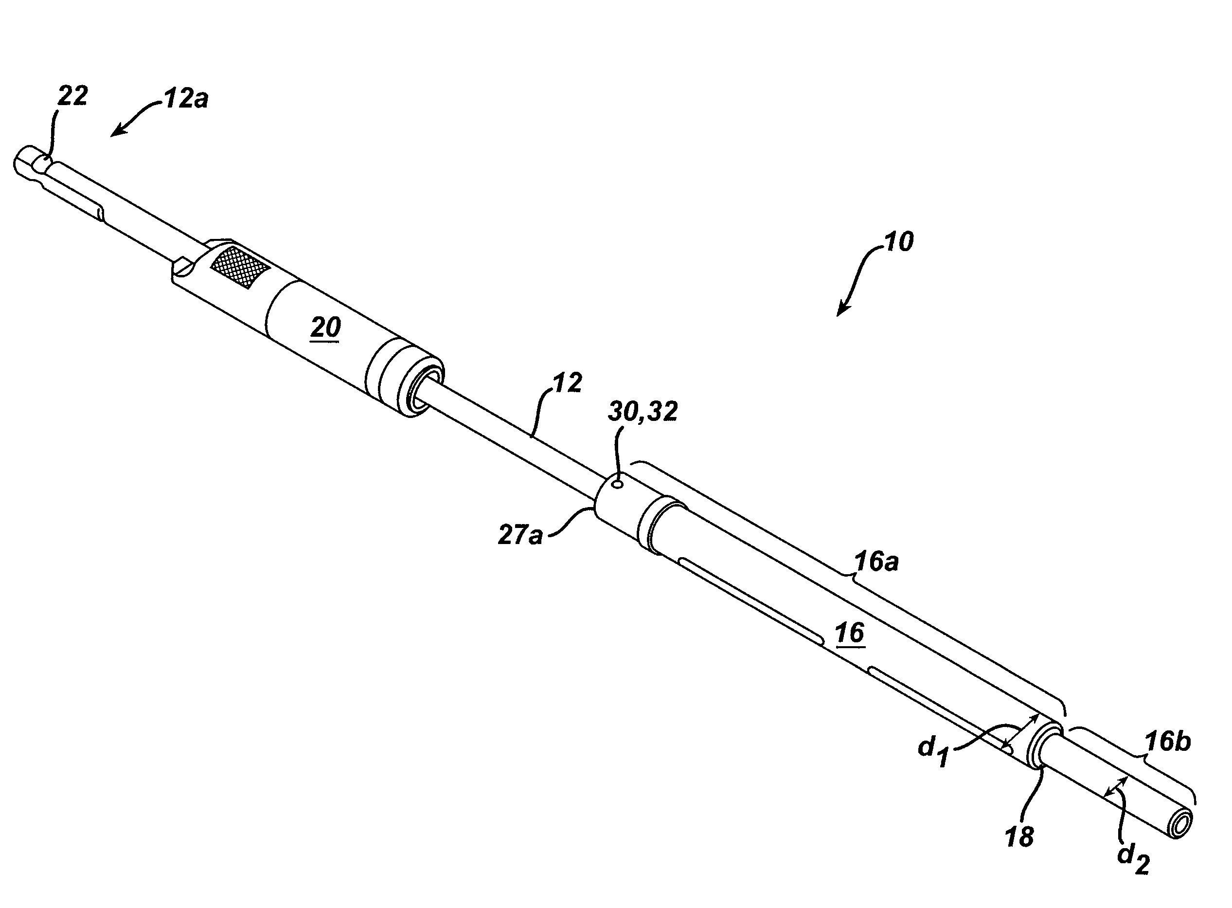
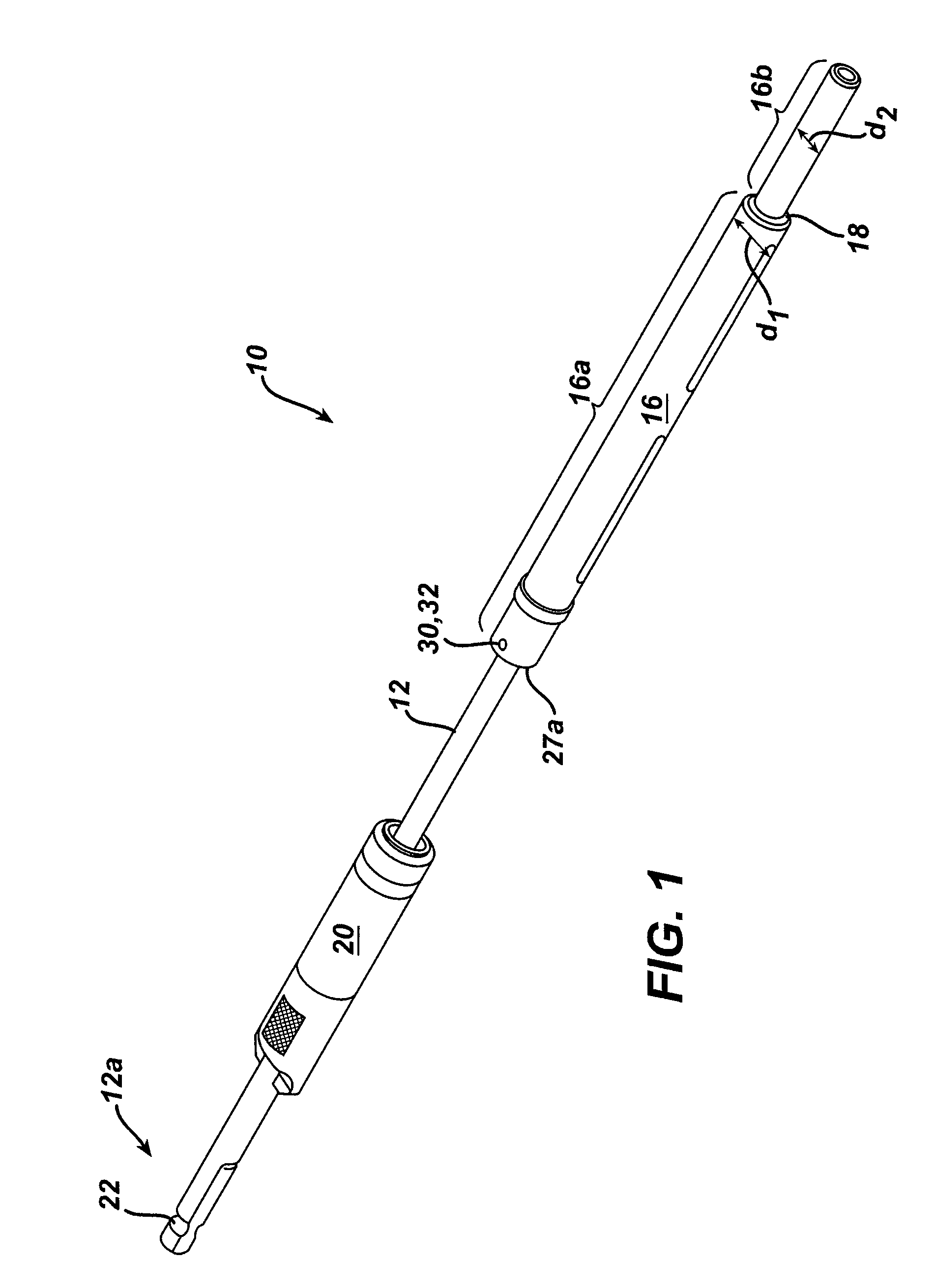
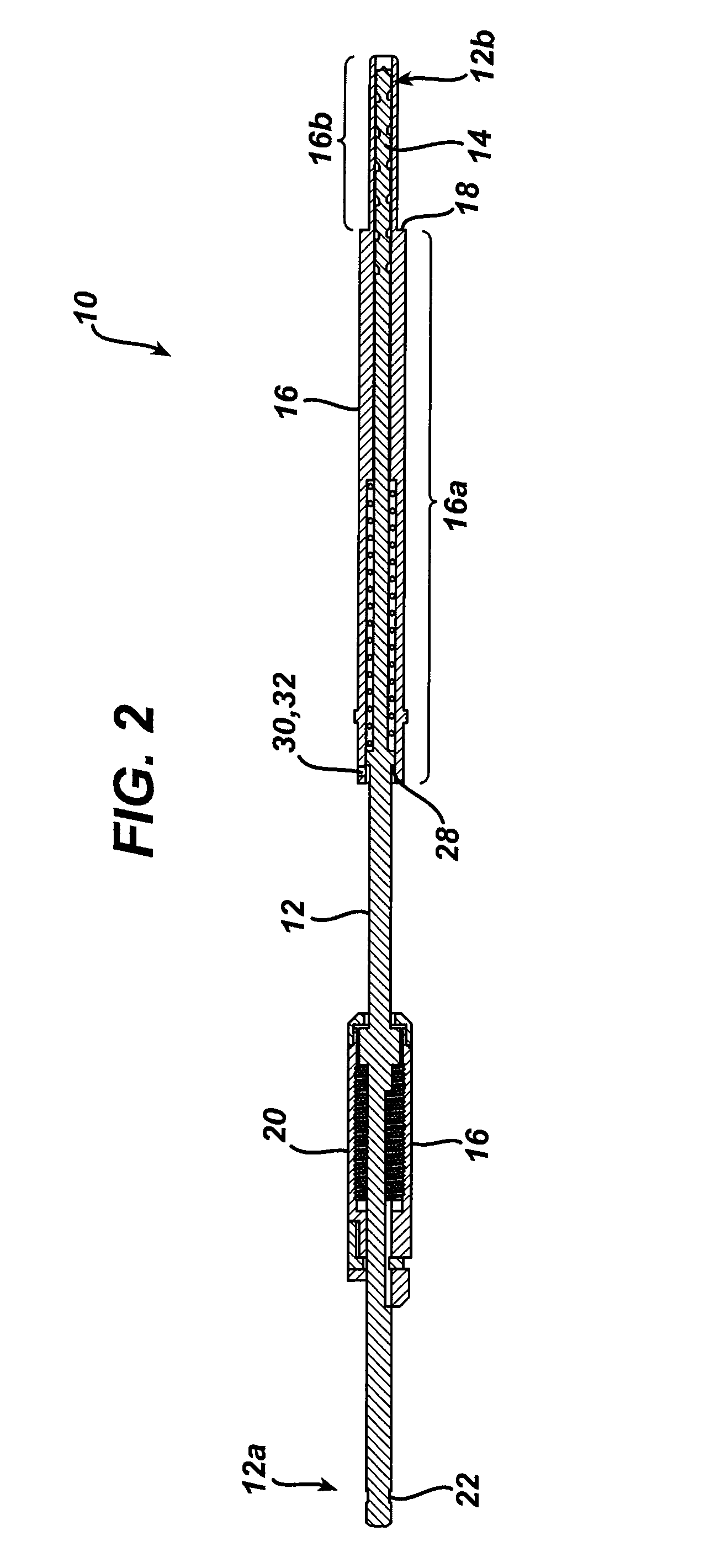
[0022]As shown in FIGS. 1 and 2, the present invention generally provides a surgical drill assembly 10 that includes an elongate shaft 12 having a proximal end 12a that is adapted to mate to a driver mechanism, and a distal end 12b having a bone preparation element 14 formed thereon. An elongate, hollow sleeve 16 is coupled to, but slidably disposed around at least a portion of the elongate shaft 12. The hollow sleeve 16 includes a stepped region 18 that is positioned between proximal and distal portions 16a, 16b such that the distal portion 16b has an outer diameter d2 that is less than an outer diameter d1 of the stepped region. The device 10 can also optionally include a stop member 20 that is effective to the limit penetration depth of the bone preparation element 14 into bone.

[0023]In use, the stepped region 18 will allow the distal portion 16b of the sleeve 16 to be disposed within a lumen in a drill guide device, while the stepped region 18 abuts the drill guide device. Guide...


PUM


Abstract

A surgical drill assembly is provided that includes an elongate shaft having a proximal end adapted to mate to a driver mechanism, and a distal end having a bone preparation element formed thereon. An elongate, hollow sleeve is coupled to, but slidably disposed around at least a portion of the elongate shaft. The hollow sleeve includes a stepped region that is positioned between proximal and distal portions such that the distal portion has an outer diameter that is less than an outer diameter of the stepped region to allow the distal portion to be disposed within a lumen in a drill guide, and the stepped region to abut the drill guide. In use, the elongate, hollow sleeve is effective to longitudinally align the elongate shaft therein during a surgical procedure. The elongate shaft can also optionally include a stop member that is effective to limit penetration depth of the bone preparation element with respect to the hollow sleeve.

Description

FIELD OF THE INVENTION[0001]This application relates to tools for use in spinal surgery, and in particular to a variable depth drill having a self-centering sleeve.BACKGROUND OF THE INVENTION[0002]Advancing age, as well as injury, can lead to changes in the bones, discs, joints, and ligaments of the spine, producing pain from nerve root compression. Under certain circumstances, alleviation of pain can be provided by performing a spinal fusion. This is a procedure that involves joining two or more adjacent vertebrae with a bone fixation device so that they no longer are able to move relative to each other. For a number of known reasons, bone fixation devices are useful for promoting proper healing of injured or damaged vertebral bone segments caused by trauma, tumor growth, or degenerative disc disease. The external fixation devices immobilize the injured bone segments to ensure the proper growth of new osseous tissue between the damaged segments. These types of external bone fixatio...

Claims


Application Information

Patent Timeline
Patent Type & Authority Patents(United States)
IPC IPC(8): A61B17/00A61B17/16A61B17/17A61B19/00
CPCA61B17/1617A61B17/1671A61B17/1728A61B17/1757A61B17/1633A61B2019/304A61B2090/034
Inventor FANGER, JONATHANKOLB, ERIC D.FESSLER, RICHARD
Owner DEPUY SPINE INC (US)
Why Eureka
Try Eureka