GPS receiver

a global positioning system and receiver technology, applied in the field of global positioning system (gps) receivers, can solve the problems of large error in measured position, inability to obtain measurement solutions, and significant influence of error signals on measurement, so as to improve the probability of positioning and improve the applicability. , the effect of good balan

Inactive Publication Date: 2006-11-28
ALPINE ELECTRONICS INC
View PDF3 Cites 27 Cited by
  • Summary
  • Abstract
  • Description
  • Claims
  • Application Information

AI Technical Summary

Benefits of technology

[0018]To solve the foregoing problems, the invention has a main object to provide a GPS receiver that can measure a position of interest using GPS satellite signals with as high accuracy as possible by appropriately setting a threshold of a reception level of the signal from each GPS satellite and a DOP threshold based on an interrelation between the satellites.
[0020]Conventionally, when too much importance is placed on the reception level, a sufficient number of satellite signals to measure the position may not be available, or a good satellite constellation may not be obtained, whereby the result of measurement may often be affected by the DOP value, leading to large errors in the measured position. In contrast, in the invention, a condition in which a positioning solution is first obtained by gradually relaxing the thresholds of the reception level and of the DOP value is set as the most optimal measurement condition, where the best measurement solution can be obtained. This eliminates as many error signals as possible in the all-in-view reception mode, but relaxes the DOP threshold value with increased signal errors, following a middle course between both optimal conditions of the reception level and of the DOP value.
[0036]In the invention, the higher initial threshold is pre-set for the reception level of the signal received as mentioned above, thereby preventing the use of the GPS satellite signal including error components influenced by a multipath, obstacles in a propagation path, or noise. This results in a high-accuracy result of the positioning calculation, thus decreasing fluctuations in positioning data. In addition, a higher-accuracy positioning solution can be provided, taking into consideration the DOP value.
[0039]The reception method involves gradually relaxing the DOP threshold as well as the reception level threshold as mentioned above. This can provide the substantially optimal high-accuracy positioning solution in the condition where a good balance between both the reception level and the DOP value is achieved.
[0040]When the condition for generating or sending the positioning calculation is relaxed, the positioning information with the positioning condition attached thereto is transmitted to the host side, where the positioning data received can be appropriately utilized, taking into consideration the reliability of the positioning information. By notifying the host of the high-accuracy positioning solution, a low-reliability case, or the like, the positioning information can serve more uses. The use of the above-mentioned method may sacrifice the positioning precision, but can improve the probability of positioning. The positioning data is dealt with considering the positioning condition, thereby improving its applicability.

Problems solved by technology

Thus, the signal attenuated or lacking in data due to a multipath wave or obstacles in a propagation path, or the signal affected by noise may also be included in the positioning calculation, which often leads to a significant influence of error signals on the measurement, or results in an erroneous measurement calculation.
Conventionally, when too much importance is placed on the reception level, a sufficient number of satellite signals to measure the position may not be available, or a good satellite constellation may not be obtained, whereby the result of measurement may often be affected by the DOP value, leading to large errors in the measured position.
If this fixed condition is not satisfied, then the receiver will be in a “non-measurement” state, and thus the measurement solution cannot be obtained.

Method used


Image

  • GPS receiver
  • GPS receiver
  • GPS receiver

Examples


first embodiment

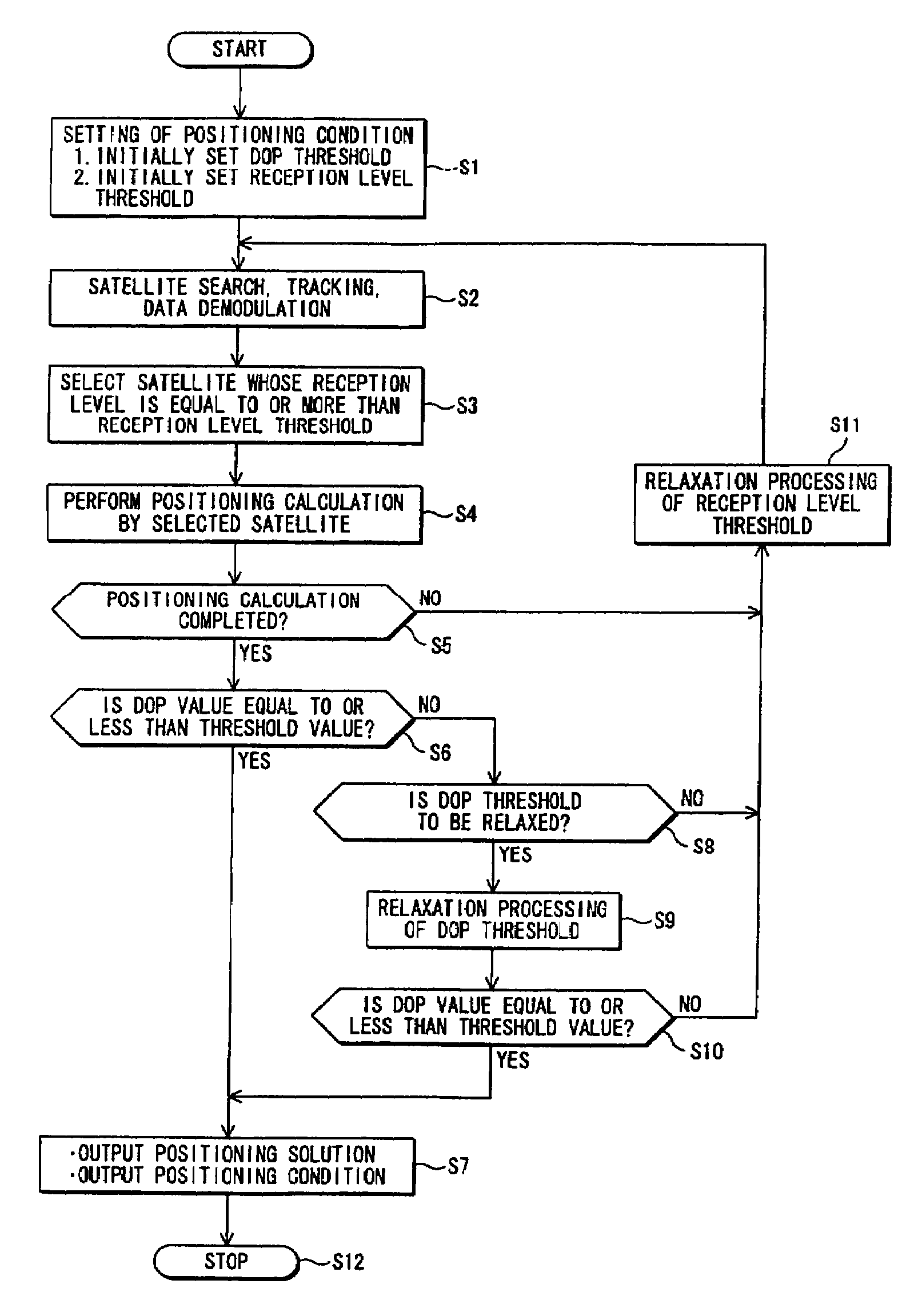
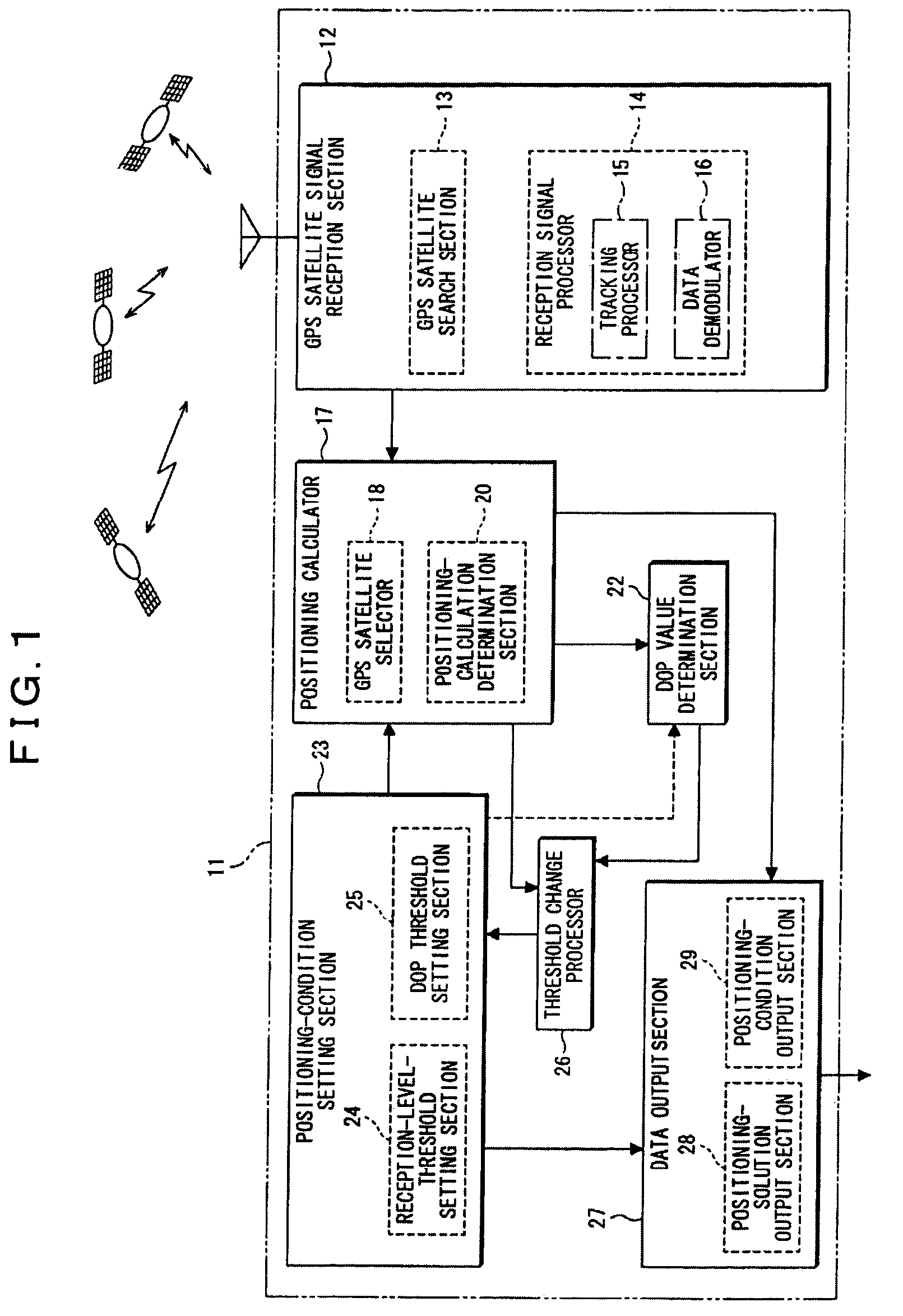
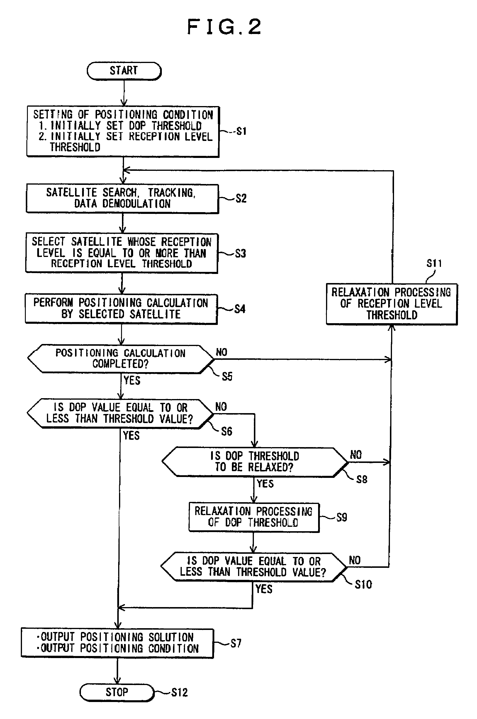
[0048]Reference will now be made in detail to the exemplary embodiment which is illustrated in the accompanying drawings. FIG. 1 is a diagram showing functional blocks for performing various functions in the GPS receiver of the embodiment, and an interrelationship among the functional blocks. Note that these functional parts or blocks serve as means for performing the respective functions.

[0049]In an example of a GPS receiver 11 shown in FIG. 1, GPS satellites designated by a GPS satellite search section 13 are searched for, and signals from the satellites are received by the GPS satellite signal reception section 12 in the all-in-view mode, in which the signals from all the visible satellites are received. The signals received are processed by a tracking processor 15, a data demodulator 16, or the like of a reception signal processor 14, and then the signals processed are sent to a positioning calculator 17.

[0050]In the positioning calculator 17, a GPS satellite selector 18 selects...


PUM


Abstract

A GPS receiver calculates a position with as high accuracy as possible by appropriately setting a threshold of a reception level of the signal from each GPS satellite and a DOP threshold based on an interrelation between the satellites. A positioning calculator performs predetermined positioning calculation using a reception signal from each satellite. When the reception level of the satellites are below a threshold set by a reception-level-threshold setting section, and thus a positioning-calculation determination section determines that the positioning cannot be performed, a threshold change processor gradually relaxes the threshold. Once relaxing the threshold enables the positioning calculation, a DOP value is determined from a constellation of the satellites used for the positioning calculation, and then is compared with a DOP threshold set by a DOP threshold setting section. If a DOP value determination section determines that the DOP threshold is not satisfied, the DOP threshold is relaxed.

Description

BACKGROUND OF THE INVENTION[0001]1. Field of the Invention[0002]The present invention relates to a global positioning system (GPS) receiver which receives a signal from a GPS satellite in measurement of a present position to measure the precise position, while capable of securely obtaining data on the present position, and to a GPS reception method using same.[0003]2. Description of the Related Art[0004]In recent years, navigation apparatus widely used in vehicles have employed one or both of a autonomous navigation method and a GPS navigation method as a measurement method in measurement of a position of a vehicle, the combination of these navigation methods being referred to as a hybrid navigation method. The autonomous navigation method involves calculating a travel distance from signals indicative of a vehicle speed or based on an acceleration sensor, and determining a rotation angle of the vehicle based on an azimuth detection sensor such as an angular speed sensor or the like,...

Claims


Application Information

Patent Timeline
Patent Type & Authority Patents(United States)
IPC IPC(8): G01S5/04H04B7/185G01C21/00G01S19/22G01S19/28
CPCG01S19/22G01S19/28
Inventor IWAMI, HIROAKI
Owner ALPINE ELECTRONICS INC
Why Eureka
Try Eureka