Driver control input device for drive-by-wire system

a technology of input device and input device, which is applied in the direction of underwater vessels, special data processing applications, and steering of non-deflectable wheels, etc., can solve the problem of hubless design, and achieve the effect of improving driving performan

Inactive Publication Date: 2006-11-28
GM GLOBAL TECH OPERATIONS LLC
View PDF30 Cites 21 Cited by
  • Summary
  • Abstract
  • Description
  • Claims
  • Application Information

AI Technical Summary

Benefits of technology

[0014]Vehicle braking force or acceleration may be relative to the force applied to the braking ring, acceleration ring or acceleration button. Preferably, when a desired speed is achieved, the acceleration control device may be released, and the vehicle's speed will be maintained, such as by cruise control. In ...

Problems solved by technology

Further, the d...

Method used


Image

  • Driver control input device for drive-by-wire system
  • Driver control input device for drive-by-wire system
  • Driver control input device for drive-by-wire system

Examples


Embodiment Construction

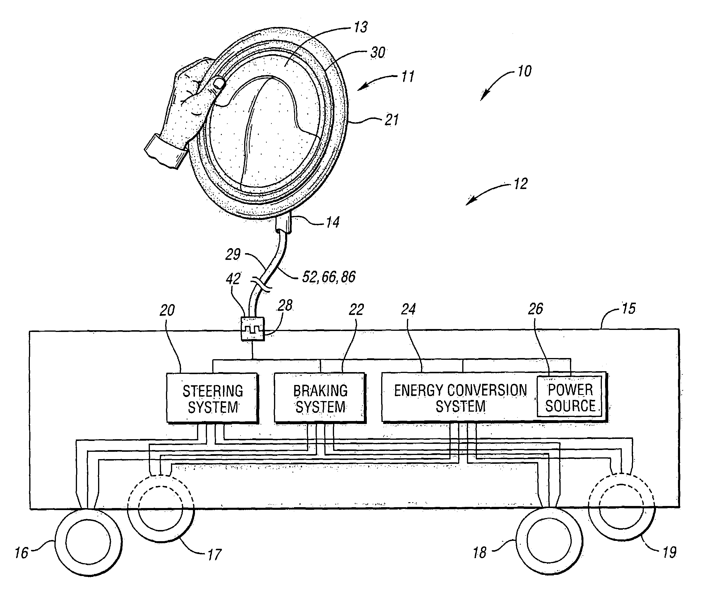
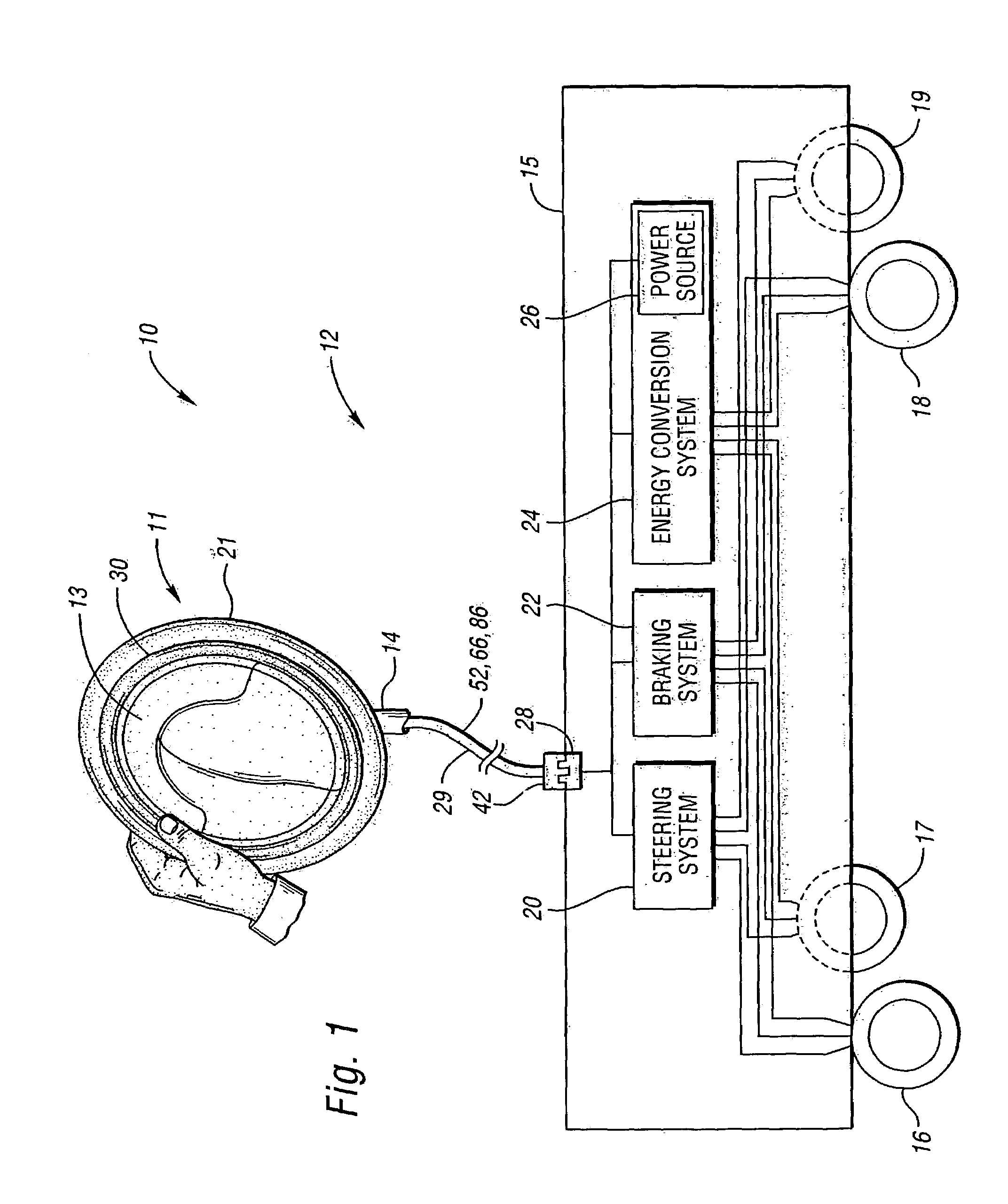
[0034]Referring to FIG. 1, a vehicle 10 in accordance with the invention includes a vehicle drive system 12 and a chassis 15. The vehicle drive system 12 includes a driver control input device 11 which is operatively connected with a steering system 20, braking system 22 and energy conversion system 24. The chassis 15 includes a frame and has four wheels 16, 17, 18, 19 that are operable with respect to the chassis 15. The vehicle 10 is preferably an automobile, but the invention also contemplates that the vehicle may be a tractor, fork-lift or other industrial vehicle. Further, the driver control input device 11 may be used in a driving simulator, aircraft, wheelchair, video game, etc.

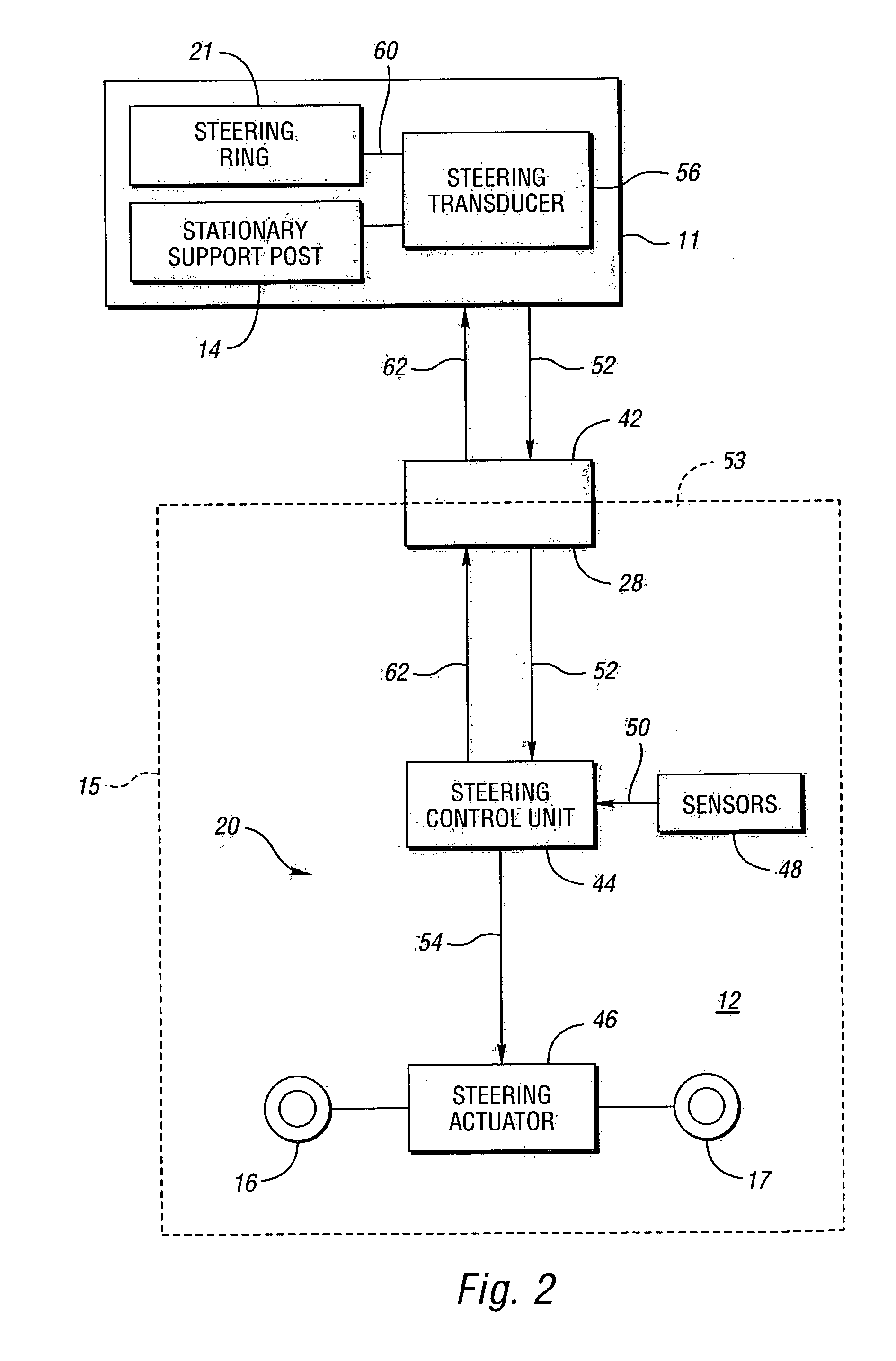
[0035]As shown, the driver control input device 11 includes a steering wheel hub 13 which is rotatable with respect to a support post 14. A steering ring 21 is supported by, and rotates with, the hub 13. A steering transducer, shown in FIG. 2, generates non-mechanical steering control signals 52 as the...


PUM


Abstract

A driver control input device includes a support post and a steering ring rotatably supported with respect to the support post. A steering transducer is operatively connected between the steering ring and support post to convert mechanical rotation of the steering ring into non-mechanical steering control signals to be sent to a steer-by-wire system. A braking ring and acceleration ring may also be provided for generating non-mechanical braking and acceleration control signals.

Description

TECHNICAL FIELD[0001]The present invention relates to a vehicle driver control input device for providing steering, acceleration and braking signals on a drive-by-wire vehicle.BACKGROUND OF THE INVENTION[0002]The implementation of drive-by-wire technology in the automotive industry (e.g. steer-by-wire, brake-by-wire, throttle-by-wire, shift-by-wire, etc.) is a result of continuing efforts to reduce cost, increase reliability, and reduce weight.[0003]In drive-by-wire systems, mechanical devices with linkages and mechanical connections are being replaced with sensors, actuators and electronics. For example, in a conventional steering system, which consists of a steering wheel, a steering column, a power assisted rack and pinion system, and tie rods, the driver turns a steering wheel which, through the various mechanical components, causes the road wheels of the vehicle to turn. In a steer-by-wire system, a number of the mechanical components between the steering wheel and the road whe...

Claims


Application Information

Patent Timeline
IPC IPC(8): B62D5/04B60K26/02B60K37/06B60R16/02B60R16/027B60T7/02B60W30/18B62D1/04B62D1/06
CPCB60K37/06B60K41/28B60R16/027B60T7/02B60T7/085B60W30/18B62D1/046B62D1/06B60K26/02B60K2350/928B60K2741/003B60K2741/28B60T2270/82B60W10/04B60W10/18B60W10/20B60W2050/146B60W2510/20B60W2520/105B60W2710/18B60K2370/782
Inventor BORRONI-BIRD, CHRISTOPHER E.CHERNOFF, ADRIAN B.EMBACH, JAMES THOMASMONTOUSSE, JULIENSHABANA, MOHSEN D.SZCZERBA, JOSEPH F.
Owner GM GLOBAL TECH OPERATIONS LLC
Why Eureka
Try Eureka