Double network reticulated frame structure

a frame structure and network technology, applied in the direction of couplings, branching pipes, rod connections, etc., can solve the problems of limited span capability of single layer structures, undesirable high-profile roof systems, and inability to meet the needs of high-profile roof systems, so as to reduce the number of diagonal connectors, reduce the number of nodal frequency and connectivity patterns, and simplify the effect of efficiency

Inactive Publication Date: 2006-12-05
CST INDS
View PDF20 Cites 29 Cited by
  • Summary
  • Abstract
  • Description
  • Claims
  • Application Information

AI Technical Summary

Benefits of technology

[0016]The invention is related to a structural system and method for building simpler and more efficient double network reticulated frame structures. The double network reticulated structural system of the invention includes a reticulated external network and a reticulated internal network that has a lower strut frequency than the external network, and substantially the same nodal frequency and connectivity pattern as the external network. The internal and external networks are substantially parallel to each other and are separated by a plurality of diagonal struts. The lower strut frequency of the internal network helps reduce the number of diagonal connectors and the overall weight, manufacturing cost, and construction time of the structure. The diagonal struts are connected to the inner and outer networks in an alternating manner along two directions to define a two-way grid such that diagonal struts in one direction are not directly connected to diagonal struts in the other direction. By connecting the diagonal struts in such an alternating pattern, no more than two diagonal struts intersect the external or internal network at any given joint.

Problems solved by technology

However, single layer systems have limited span capabilities due to buckling.
High profile roof systems are undesirable from an aesthetic point of view because they become the predominant element of the building and become an obstacle to changing the building appearance.
The span capability of double layer structures, while greater than single layer structures, is still limited by a number of factors.
The ability of structural members and connections to transfer force is often the main factor limiting the span capability of systems such as those developed by Lopez and Richter.
Welding of aluminum is not only costly, but significantly weakens the parent metal and makes the area adjacent to the weld brittle.
Furthermore, the pipe attachment method used by Lopez and Richter type systems results in a very crowded joint.
The crowded joint limits the size of the pipe that can be used between the upper and lower networks.
As such, these systems have limited capacity to transfer loads between networks (due to the reduced pipe size and welded connection strength), and have limited bending strength due to the system depth limitations that result directly from the pipe size limitation.
The limited load carrying capacity of the diagonal pipe strut connections in Richter and Lopez type systems limits the system depth and the ability of designers to optimize them.
A system with a low load carrying capacity in one of its elements cannot be effectively optimized.
As a result of the low load carrying capacity of the pipe connections, the use of Lopez and Richter type systems in the design of large span structures often result in structures that have a less than optimum number of joints and struts.
While existing double network designs address some of the problems associated with single network structures, the double network structures themselves are not without drawbacks and shortcomings.
For example, presently available double network structures often make inefficient use of struts, joints, and network depth.
In addition to making the structure heavier, the extraneous struts may increase the number of connections required at the nodal joints, resulting in an overly complicated system.

Method used


Image

  • Double network reticulated frame structure
  • Double network reticulated frame structure
  • Double network reticulated frame structure

Examples


Embodiment Construction

[0032]Following is a detailed description of exemplary embodiments of the invention wherein reference numerals for the same and similar elements are carried forward throughout the various figures. It should be noted that the figures are provided here for illustrative purposes only and should not be taken as drawn to any particular scale.

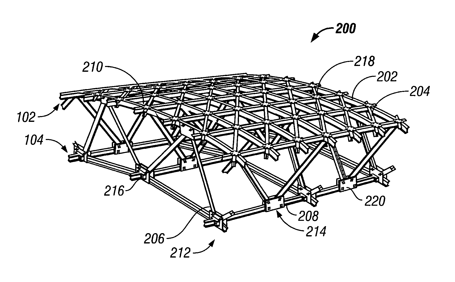
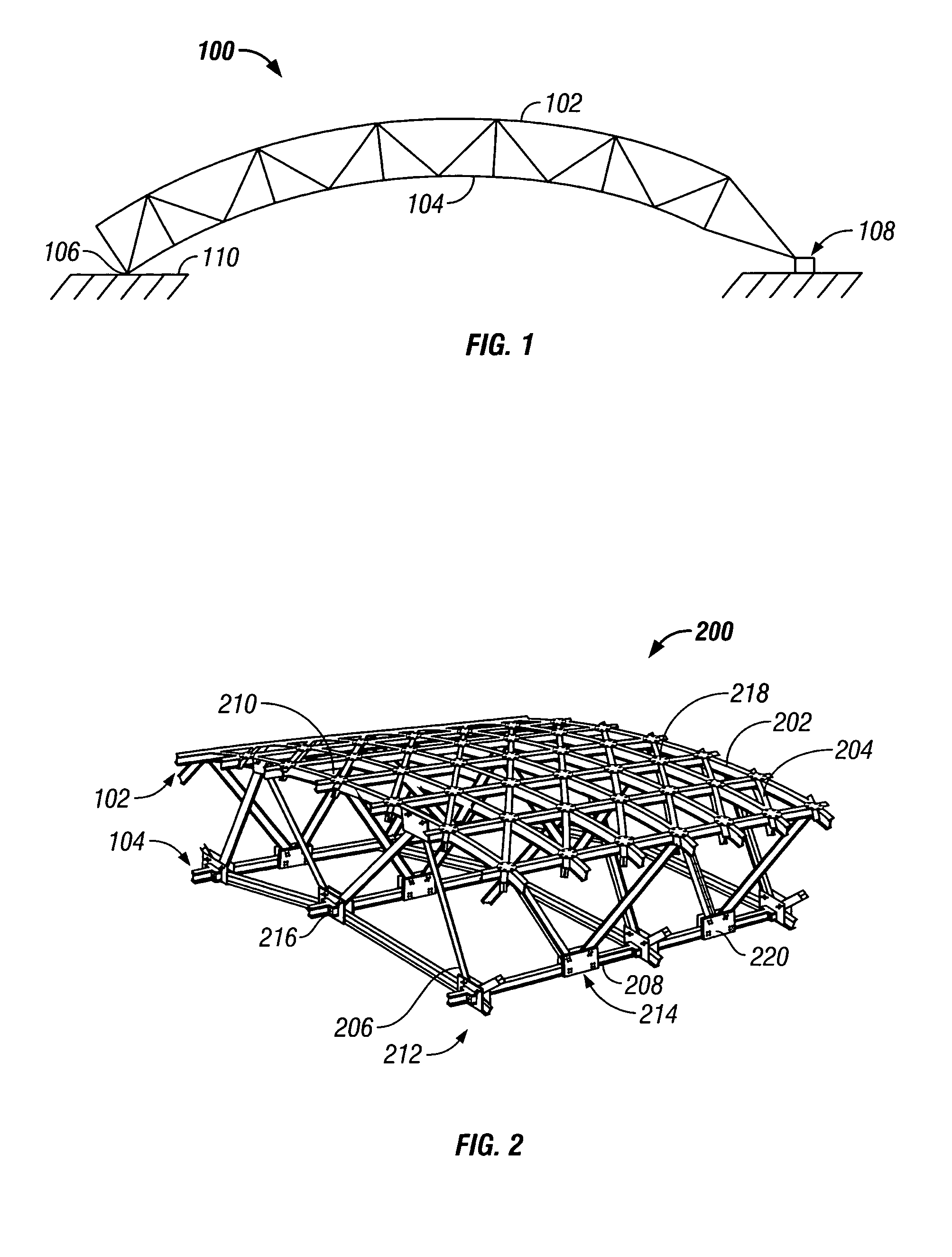
[0033]Referring now to FIG. 1, a side view is shown of an exemplary reticulated frame structure 100 according to embodiments of the invention. As can be seen, the reticulated structure is a double network structure that includes an external network 102 and an internal network 104. The external network 102 and internal network 104 are usually similarly shaped so that a curvature at any corresponding points on the network surfaces is defined by the same center of curvature. The curvature of the reticulated frame structure 100 may be a constant, single curvature of the kind that might be used in a roof for a stadium, sporting arena, and the like. Other ...


PUM


Abstract

Structural system and method are disclosed for building a simpler and more efficient double layer reticulated frame structure. The double layer reticulated frame structure includes an internal network that has a lower strut frequency than the external network. The lower strut frequency helps reduce the overall weight, cost, and construction time of the structure. Diagonal struts space apart and connect the internal and external networks. The diagonal struts are connected in an alternating manner such that no more than two diagonal struts are connected together at any point.

Description

PRIOR RELATED APPLICATIONS[0001]Not applicable.FEDERALLY SPONSORED RESEARCH STATEMENT[0002]Not applicable.FIELD OF THE INVENTION[0003]The invention is related to reticulated frame structures and, more particularly, to a structural system and method for building a dual network reticulated frame structure of the kind used for the construction of stadia and sport arenas.BACKGROUND OF THE INVENTION[0004]Multi-purpose sports arenas and stadia built around the world are often covered with space frames and lattice structures for weather protection, climate control, and acoustic enhancement. The basic shape of this type of cover, apart from local features of the surface, is usually a portion of a surface of a revolution, such as a portion of a sphere, cylinder, ellipsoid, and the like. Other kinds of surface contours have been and can be used.[0005]One approach to the design of domes or arena roof covers is to use a single network comprised of interconnected structural members, or struts. T...

Claims


Application Information

Patent Timeline
Patent Type & Authority Patents(United States)
IPC IPC(8): E04B7/08
CPCE04B1/19E04B1/32E04B1/3205E04B1/1903E04B1/1909Y10T403/347E04B2001/1936E04B2001/3241E04B2001/3247E04B2001/3252
Inventor LOPEZ, ALFONSO
Owner CST INDS
Why Eureka
Try Eureka