Combined air separation natural gas liquefaction plant

a natural gas liquefaction and air separation technology, applied in the field of combined air separation natural gas liquefaction plant, can solve the problems of increasing irreversibility and achieve the effects of avoiding or minimising recycling, increasing cooling, and high power consumption

Active Publication Date: 2006-12-05
LAIR LIQUIDE SA POUR LETUDE & LEXPLOITATION DES PROCEDES GEORGES CLAUDE
View PDF17 Cites 113 Cited by
  • Summary
  • Abstract
  • Description
  • Claims
  • Application Information

AI Technical Summary

Benefits of technology

[0010]It is an object of this invention to provide a process to liquefy natural gas in combination with an air separation unit with isentropic expansion and without having such a high power consumption. The invention consists in using the cold that can be generated by the air separation, unit through isentropic expansion preferably together with liquid vaporisation in order to liquefy natural gas. The basic idea consists in using the cold streams removed from the distillation section under liquid or gaseous form, enriched in nitrogen, oxygen or argon in order to cool the natural gas by indirect heat exchange. As the heat for warming those cold streams is no longer fully available to cool down the air, isentropic expansion is used to cool down directly the air. Another solution consists in performing isentropic expansion on one of the cold streams in order to increase the quantity of cooling provided by the cold streams and therefore be able to cool down natural gas and air. Air expansion will be the preferred solution because recycling can be either avoided or minimised. Generally, recycling increases the duty of an heat exchanger therefore increasing its irreversibility.
[0012]A process as per the invention will benefit from the following advantages as compared to the cascade or mixed refrigerant cycle or a combination of the two which have been used in all the baseload plants to date:
[0013]1. the problem of distributing vapor and liquid phases in the heat exchanger is basically eliminated; therefore, it will be possible to use brazed aluminium heat exchangers which are more efficient and less expensive than classical spiral wound exchangers; they also allow more streams in the heat exchanger;
[0014]2. temperature control is much easier when a gas is expanded;
[0016]4. tolerance to variation in composition of the feed is higher;

Problems solved by technology

Generally, recycling increases the duty of an heat exchanger therefore increasing its irreversibility.

Method used


Image

  • Combined air separation natural gas liquefaction plant
  • Combined air separation natural gas liquefaction plant
  • Combined air separation natural gas liquefaction plant

Examples


Embodiment Construction

[0049]Several embodiments of the invention are possible:

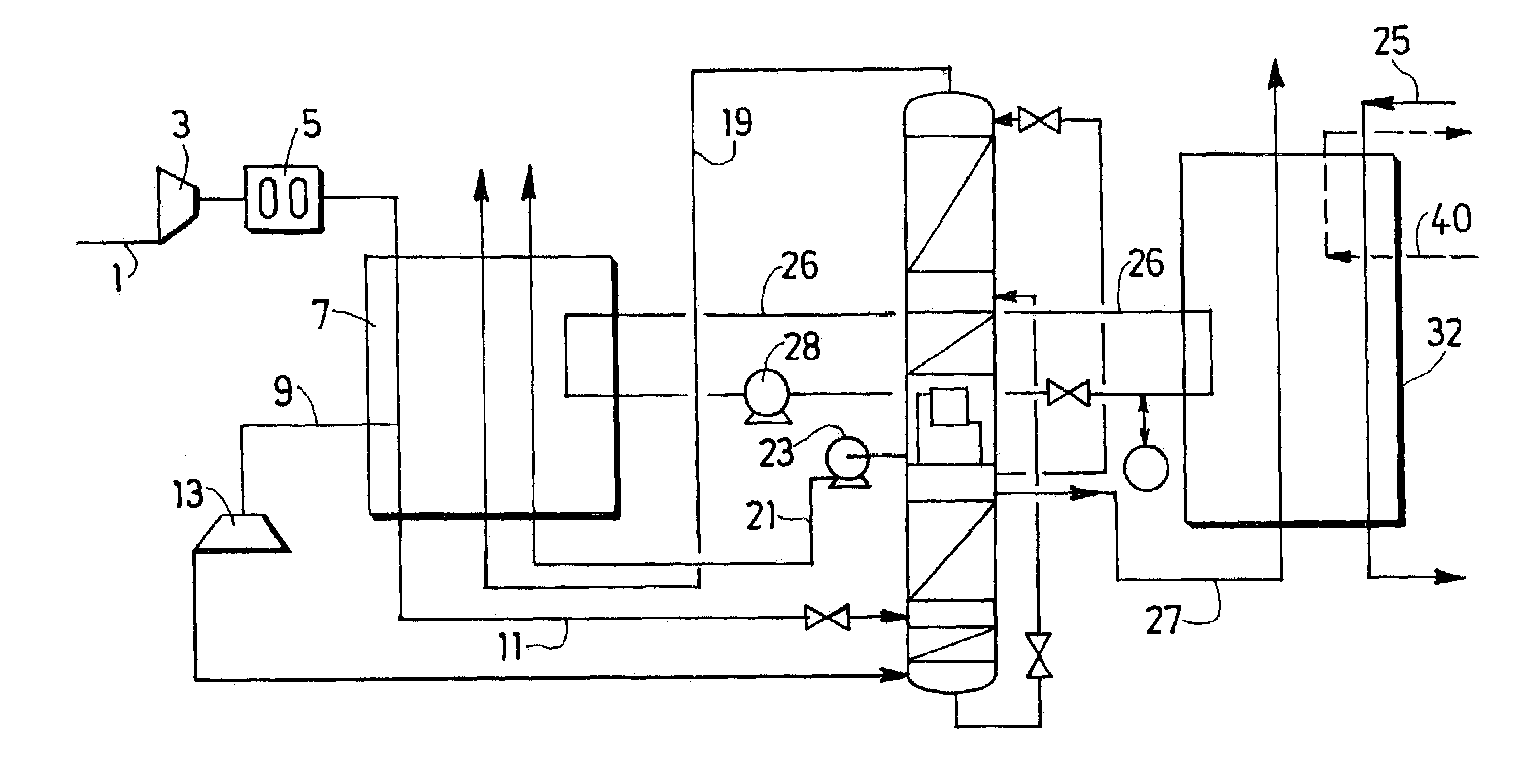
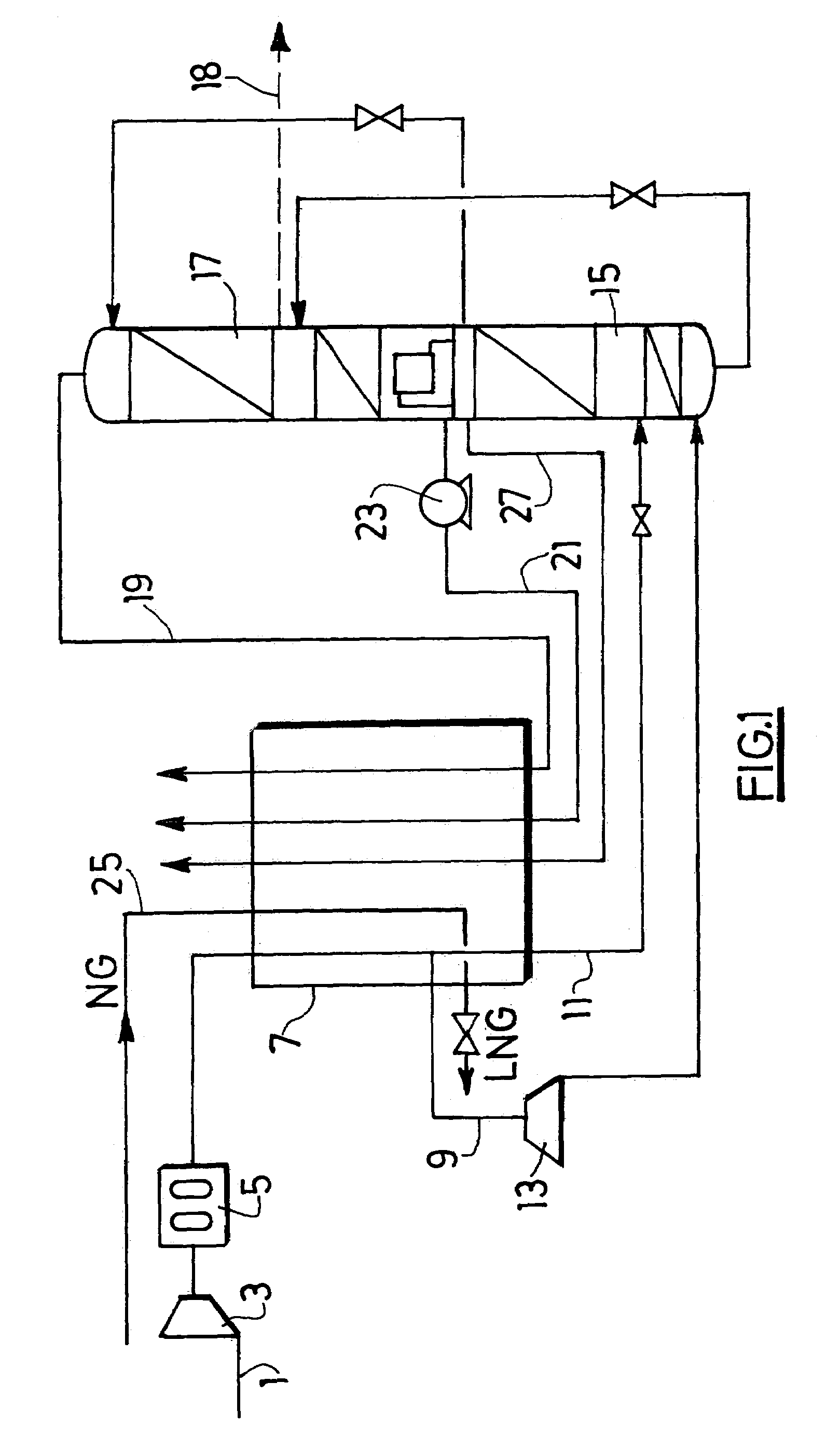
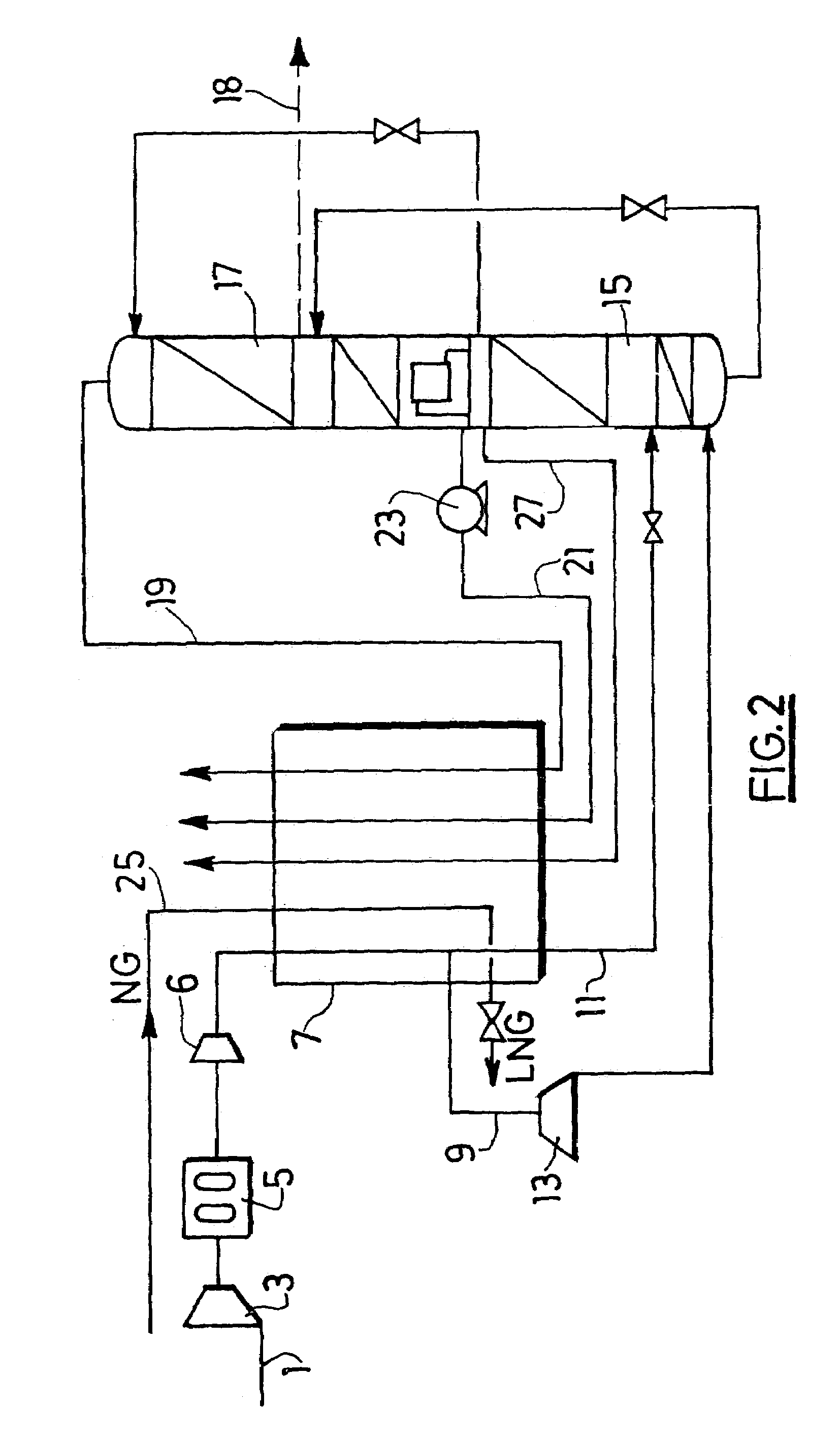
[0050]Minimal LNG production using the installation of FIG. 1. In this case, the GTL plant is typically constructed near an existing / future LNG baseload plant in order to benefit from its infrastructures.

[0051]Air 1 is compressed in a main air compressor 3 to a pressure of 21.5 bar. and is cooled through the use of a mechanical refrigeration unit or an absorption refrigeration unit to a temperature of 12° C. Air 1 is then purified through adsorbers 5 containing typically and molecular sieve and impurities like water and CO2 are removed. A low temperature for the purification unit is preferred for several reasons air will enter the main heat exchanger at a lower temperature allowing an increase in the LNG production, air will content less water and adsorption is more efficient therefore less alumina and molecular sieve will be required. Air 1 (base=1000 Nm3 / h) is then introduced in a main heat exchanger 7 typically of the plate-...


PUM

PropertyMeasurementUnit
temperatureaaaaaaaaaa
temperaturesaaaaaaaaaa
temperatureaaaaaaaaaa

Abstract

In an integrated process and apparatus for the separation of air by cryogenic distillation and liquefaction of natural gas in which at least part of the refrigeration required to liquefy the natural gas is derived from at least one cryogenic air distillation plant comprising a main heat exchanger (7) and distillation columns (15, 17), wherein the natural gas (25) liquefies by indirect heat exchange in a heat exchanger (7, 32, 34) with a cold fluid (21, 26), the cold fluid being sent to the heat exchanger at least partially in liquid form and undergoing at least a partial vaporisation in the heat exchanger.

Description

CROSS-REFERENCE TO RELATED APPLICATIONS[0001]This application claims the benefit under 35 U.S.C. § 119(e) to provisional application No. 60 / 423,039, filed Nov. 1, 2002, the entire contents of which are incorporated herein by reference.BACKGROUND OF THE INVENTION[0002]Natural gas is often unavailable in regions where consumers are located, making it necessary to move the natural gas from remote areas. Currently, there are four (4) methods for moving the natural gas between locations: transport by pipeline, liquefaction of the light hydrocarbon, conversion of natural gas to a liquid or solid product to allow for transport, and conversion of natural gas to electricity for transport by cable. Each of these methods has its limitations.[0003]Transport by pipeline is a highly popular method for transport. However, this may not be feasible due to the extreme distances between natural gas resources and consumers, which increases cost.[0004]Liquefaction of the light hydrocarbon allows for sev...

Claims


Application Information

Patent Timeline
Patent Type & Authority Patents(United States)
IPC IPC(8): F25J1/00F25J3/00C10L3/06C10L10/14F25J1/02F25J3/04F25J5/00
CPCF25J1/0022F25J1/0042F25J1/005F25J1/0052F25J1/007F25J1/0087F25J1/0204F25J1/0205F25J1/0221F25J1/0222F25J1/0234F25J1/0236F25J3/0409F25J3/04127F25J3/04157F25J3/04218F25J3/04296F25J3/04345F25J3/04387F25J3/04412F25J3/04539F25J3/04606F25J3/04612F25J3/04963F25J3/04224F25J2210/42F25J2210/50F25J2210/60F25J2240/10F25J2270/90F25J2270/906
Inventor TRANIER, JEAN-PIERRE
Owner LAIR LIQUIDE SA POUR LETUDE & LEXPLOITATION DES PROCEDES GEORGES CLAUDE
Why Eureka
Try Eureka