Method and apparatus for solar collector with integral stagnation temperature control
- Summary
- Abstract
- Description
- Claims
- Application Information
AI Technical Summary
Benefits of technology
Problems solved by technology
Method used
Image

Examples
example 1
Design Criteria for Stagnation Control in a Typical Solar Collector
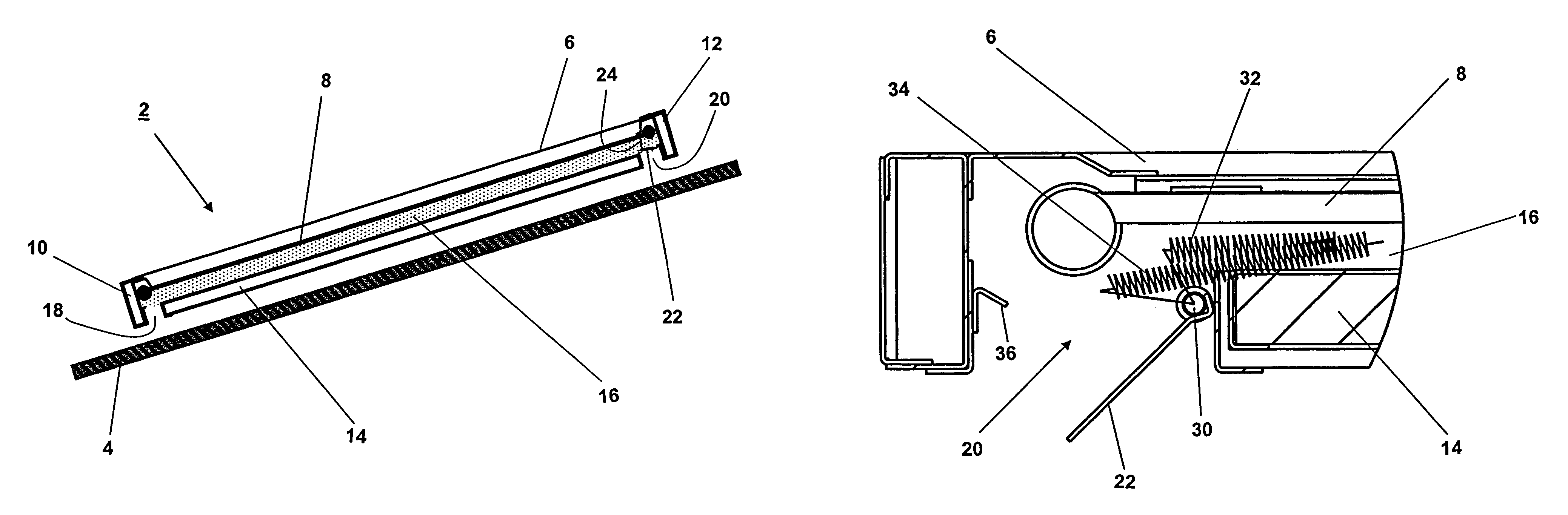
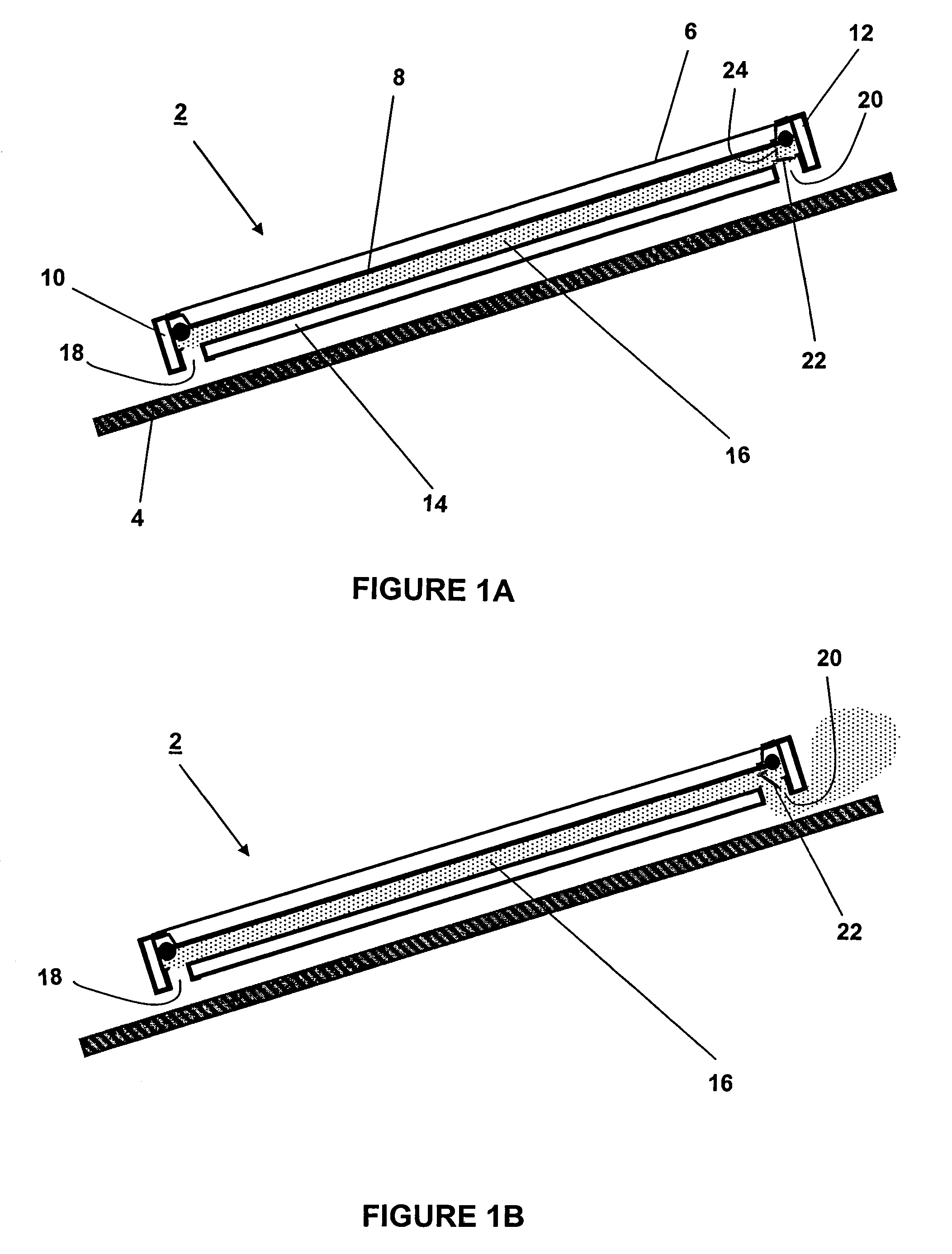
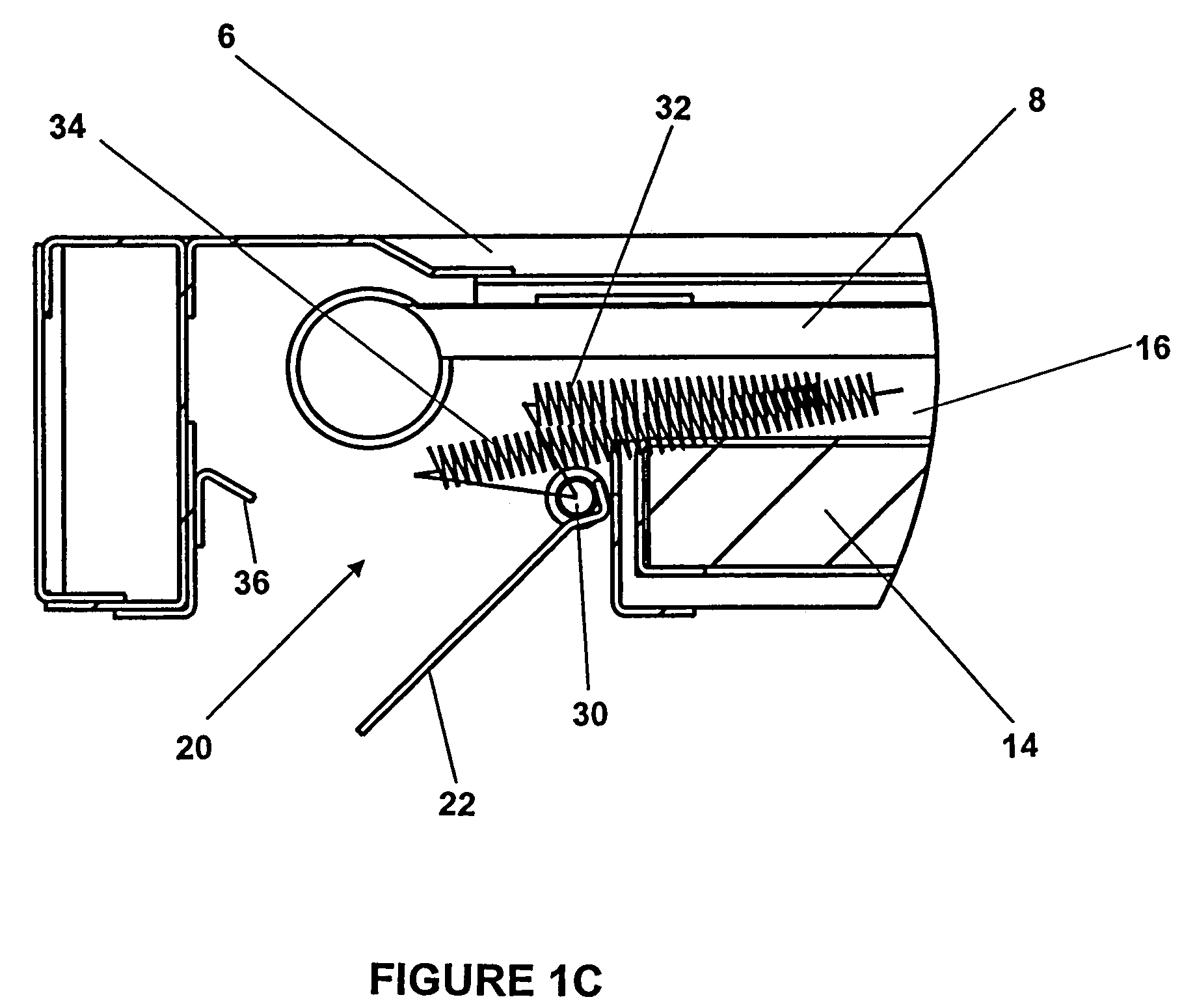
[0054]This example presents design considerations for high stagnation temperature control in a conventional solar collector mounted at an 18° slope (i.e., a typical North American roof slope). However, it will be appreciated that the analysis can be applied to different solar collector types at different mounting slopes and in different geographic locations.
[0055]An analysis of typical weather data (obtained from Environment Canada) for North American cities, representing different geographical regions, shows that solar radiation levels (on a 18° tilted surface) greater than 1000 W / m2 typically occur 45 h / yr in Canada and 78 h / yr in the southern United States. Ambient temperatures greater than 30° C. represent less than 60 h / yr in Canada but could reach 856 h / yr in the southern United States. The coincidence of solar radiation levels greater than 1000 W / m2, with periods of high temperature (i.e., >30° C.), is less fr...
example 2
Design and Evaluation of the Venting Channel
[0062]To predict the magnitude of the cooling effect and to optimize the design of the venting channel, computer modeling and simulation using a Computational Fluid Dynamics (CFD) program, and laboratory testing under controlled conditions, of a solar collector absorber with integral venting channel was carried out. CFD models for channels with a straight inlet and outlet and with an inlet and outlet with downward-facing 90° bends were developed. The modeling simulated the heat-flux input from the lower surface of the absorber plate to air located in a venting channel below the absorber. Heating of air below the absorber resulted in an increase in local air-temperature and a corresponding reduction in air density. The reduction in local air density created a buoyancy force that initiated a natural convection flow within the heated air below the absorber plate. As long as the heated air was allowed to exhaust from the venting channel, coole...
case 1
tive Cooling Channel
[0068]Testing was first carried out for channels of different depths and with uncoated channel surfaces that have low radiative emissivity. As such, these results are representative of cases for which convective cooling of the upper channel surface was the dominant heat transfer mechanism, i.e., radiation heat transfer played a only a small role. As well, during these tests, the bottom of the channel was not insulated. The channel temperature was measured for two tilt angles (18° and 30°) and four channel depths (10, 20, 30, and 50 mm) with the input power level set at 400 W / m2. As expected, the upper surface temperature increased along the channel from the inlet to outlet under all conditions. Results indicated that the maximum temperature on the upper surface increased only slightly as the channel depth was reduced from 50 mm to 20 mm. A considerable increase in surface temperature occurred when the channel depth was reduced to 10 mm. This result is consistent ...
PUM
 Abstract
Description
Claims
Application Information
 - Generate Ideas
- Intellectual Property
- Life Sciences
- Materials
- Tech Scout
- Unparalleled Data Quality
- Higher Quality Content
- 60% Fewer Hallucinations
Browse by: Latest US Patents, China's latest patents, Technical Efficacy Thesaurus, Application Domain, Technology Topic, Popular Technical Reports.
© 2025 PatSnap. All rights reserved.Legal|Privacy policy|Modern Slavery Act Transparency Statement|Sitemap|About US| Contact US: help@patsnap.com