Suturing device for endoscope

a suction device and endoscope technology, applied in the field of suction devices, can solve the problems of inability to retry, the curved needle cannot penetrate the target tissue deeply enough, and the suction effect of the curved line is degraded

Inactive Publication Date: 2006-12-05
APOLLO ENDOSURGERY INC +1
View PDF13 Cites 209 Cited by
  • Summary
  • Abstract
  • Description
  • Claims
  • Application Information

AI Technical Summary

Benefits of technology

[0008]In addition, the suturing device can have a needle attached on the distal end of the suturing device for suturing and fixing means provided on the distal end side of the suturing device for preventing the suturing device from dislocating from the suturing portion. Furthermore, with a needle attached on the distal end of the suturing device for suturing, fixing means may be provided on the distal end side of the endoscope for preventing the suturing device from dislocating from the suturing portion.

Problems solved by technology

According to U.S. Pat. No. 5,037,433, however, since the springy curved needle is inserted in a thin inner tube in its straightened state, a decompression force of the springy curved needle works against the inner tube when the curved needle is pushed out of the inner tube by the push rods, the puncture effect of the curved line is degraded and thus the curved needle does not penetrate into the target tissue deeply enough.
In addition, once the needle has punctured the tissue, it cannot be retried, and dislocation of the puncture cannot be corrected.

Method used


Image

  • Suturing device for endoscope
  • Suturing device for endoscope
  • Suturing device for endoscope

Examples


embodiment 1

[0055]A first embodiment of the present invention is shown in FIGS. 1 through 45, 126 through 127 and 141.

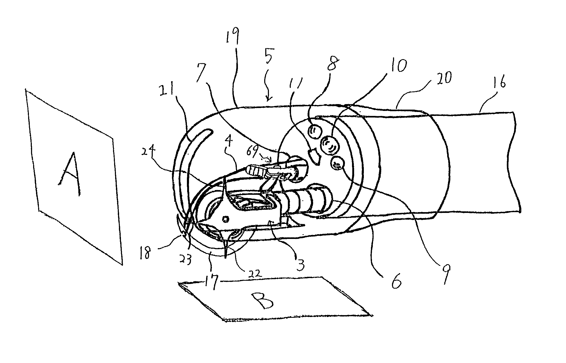
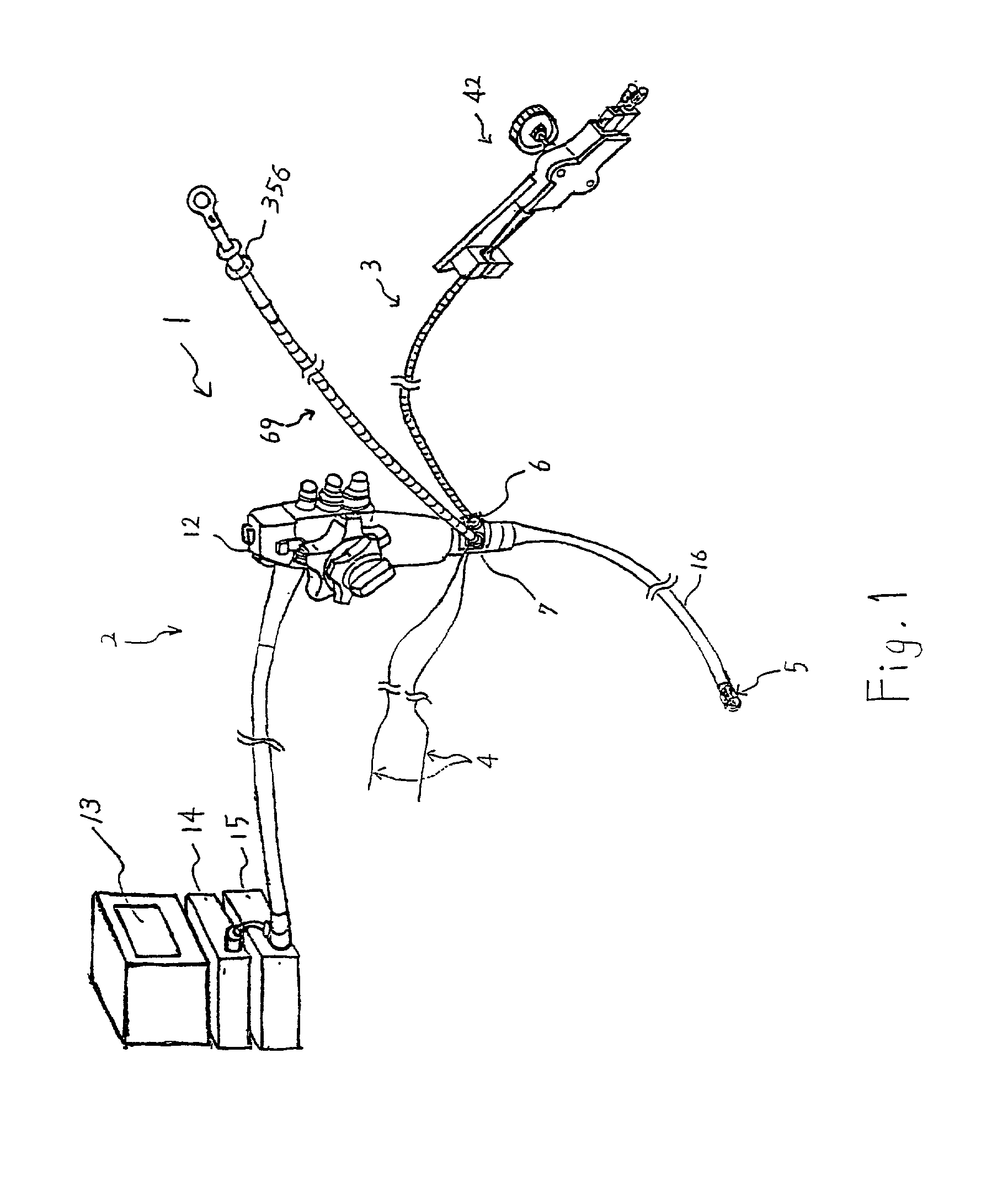
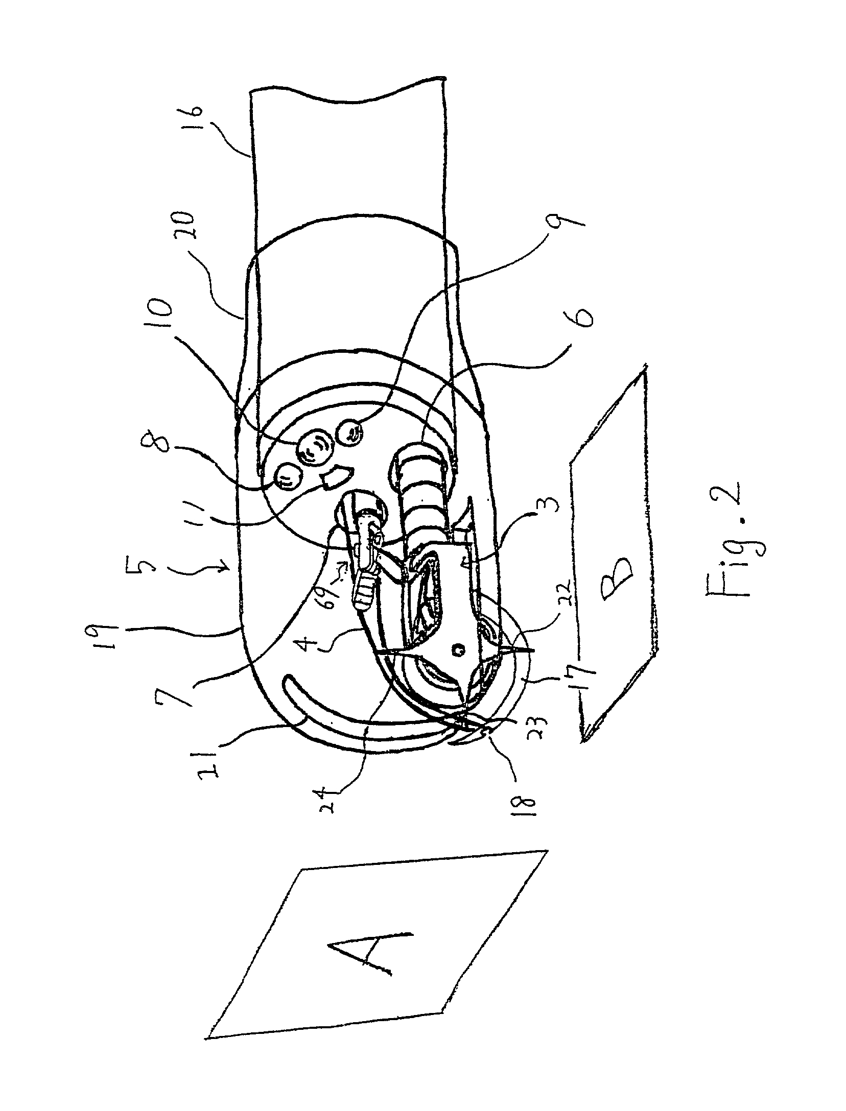
[0056]FIG. 1 shows an overall view of the endoscope suturing system 1. FIG. 2 is an enlarged view showing the distal end of the endoscope 11. As shown in FIG. 1, the suturing system 1 comprises an endoscope system 2, suturing device 3, thread 4, and tissue protective member 5. The endoscope system 2 comprises an endoscope 12, image processing unit 14, light source 15, and observation monitor 13. Although the endoscope 12 is equipped with two instrument channel ports 6 and 7, it may have only a single instrument channel port. Alternatively, an outer channel 122 may be fixed to a flexible portion 16 with a medical tape 123 or the like as shown in FIG. 122.

[0057]As shown in FIG. 2, the distal end of the endoscope is provided with a CCD camera 10, light guides 8 and 9, instrument channel ports 6 and 7, and a nozzle 11 for washing the lens of the CCD camera. Although a videoscope usi...

embodiment 2

[0103]A second embodiment of the present invention is shown in FIGS. 46 and 47.

[0104]The second embodiment has the same construction as the first embodiment, except that the curved needle 17 is replaced by the curved needle 127; therefore only the construction of the curved needle 127 is described.

[0105]FIG. 46 shows the suturing device 3 wherein the curved needle 17 shown in FIGS. 3 and 4 is replaced by the curved needle 127. FIG. 47 is a figure viewed from the arrow C in FIG. 46. As shown in FIGS. 46 and 47, a hole 128 in the rotation axial direction of the curved needle 127 is provided at the distal end of the curved needle 127.

[0106]The assembly method of the second embodiment is same as that of first except that the thread 4 is inserted through the hole 128, not hooked to the needle's slit 18. The suturing procedure is the same as that of the first embodiment except that the thread 4 is withdrawn from the hole 128, instead of being removed from the needle's slit 18.

[0107]In add...

embodiment 3

[0108]The third embodiment is shown in FIGS. 48 through 50. The third embodiment has the same construction as the first, except that the curved needle 17 is replaced by the curved needle 129; therefore only the construction of the curved needle 129 is described in the following.

[0109]FIG. 48 shows the suturing device 3 wherein the curved needle 17 shown in FIGS. 3 and 4 is replaced by the curved needle 129. FIG. 49 is a figure viewed from the arrow A in FIG. 48. FIG. 50 is a cross sectional view taken from the line BB of FIG. 49. As shown in FIGS. 48 through 50, a hole 130 oblique to the rotational trajectory of the curved needle 129 is provided at the distal end of the curved needle 129. As shown in FIG. 50, the angle θ between the rotational trajectory plane and the hole 130 may be of any angle but is desirably 45 degrees.

[0110]The assembly and suturing methods of the third embodiment are same as the assembly method of second embodiment.

[0111]In addition to the advantages of first...


PUM


Abstract

A suturing device for an endoscope includes a curved needle rotatably attached on the distal end of the suturing device. A rotary member is provided on the rotation axis of the curved needle for rotating said curved needle and a connecting arm connects the curved needle to the rotary member. The center of curvature of the curved needle is aligned with the rotation axis of the curved needle and engaging means are provided at least at the pointed end of the curved needle for receiving thread.

Description

CROSS-REFERENCE TO RELATED APPLICATIONS[0001]This application claims the benefit of U.S. Provisional Application to Tetsuya Yamamoto et al, entitled “Suturing Device for Endoscope,” application No. 60 / 296,111, filed Jun. 7, 2001.BACKGROUND OF THE INVENTION[0002]The present invention relates to a suturing device for suturing using an endoscope for the purpose of hemostasis or for suturing or shunting tissues in body cavities.[0003]In recent years, treatment using endoscopes has been drastically improving to enable various treatment of body organs without large incisions such as in open surgery. Suturing of punctures in body cavities and for hemostasis have become very important techniques among endoscopic treatment, and various methods have been attempted.[0004]U.S. Pat. No. 5,037,433, for example, discloses a construction comprising a flexible endoscope (70) disposed in one of the lumens of an outer tubular member (20), and a forceps instrument (52) having a soft inner tube (32) in ...

Claims


Application Information

Patent Timeline
Patent Type & Authority Patents(United States)
IPC IPC(8): A61B17/04A61B1/00A61B1/018A61B17/00A61B17/06A61B19/00
CPCA61B1/0008A61B17/0469A61B1/018A61B2017/00292A61B2017/003A61B2017/06042A61B2019/5206A61B2019/5217A61B2090/3614A61B2090/306
Inventor YAMAMOTO, TETSUYACHUNG, SYDNEY SHEUNG CHEEKAWASHIMA, KOICHIMURAMATSU, JUNICHISUZUKI, KEITAONUKI, YOSHIOSUGI, YOSHIHIKOKOBAYASHI, TSUKASA
Owner APOLLO ENDOSURGERY INC
Why Eureka
Try Eureka