Graft fixation system and method

a fixation system and graft technology, applied in the field of ligament or tendon reconstruction fixation system and a, can solve the problems of excess trauma to the patient receiving the graft, damage to the graft, increase in post-operative recovery time, etc., and achieve the effect of facilitating bone growth

Inactive Publication Date: 2006-12-05
AO TECH AG +1
View PDF130 Cites 147 Cited by
  • Summary
  • Abstract
  • Description
  • Claims
  • Application Information

AI Technical Summary

Benefits of technology

[0013]In another embodiment, the cage may comprise two pieces which connect together to surround a portion of the graft. The two pieces of the cage may comprise a cage bottom portion and a cage top portion attachable to the cage bottom portion. The two or more pieces forming the cage may have one or more detents configured and adapted to attach the pieces together. The pieces of the cage also may have one or more fittings configured and adapted to receive the detent. The cage also may have one or more walls or wall portions. The wall(s) or wall portion(s) may have serrations or teeth on their interior surface to assist in holding the graft. The cage further may have openings to facilitate bone growth around the cage and to the graft.
[0014]The implant body has an outer surface at least a portion of which may contain threads for implantation into bone. The opening in the implant body for the insertion tool may have a portion which is hexagonally-shaped, keyed or shaped so that the insertion tool can rotate the body. Alternatively, in addition to, or optionally, the insertion tool opening may further have a portion which includes internal threads for mating with threads on the insertion tool to assist in connecting the insertion tool to the implant.

Problems solved by technology

Known devices and methods for installing and anchoring soft tissue and bone-tendon-bone grafts suffer from inadequacies which can result in damage to the graft, excess trauma to the patient receiving the graft, and / or an increase in post-operative recovery time.
In particular, many known devices and graft fixation methods do not allow for satisfactory tensioning of the graft.
Such removal can cause the graft to tear.
Many prior art fixation devices also cause the flexible graft material to twist upon installation or when tension is adjusted.
Twisting of the graft is undesirable because it places unequal stresses on the graft, thereby lessening the probability of successful rehabilitation.
When the graft is tensioned with a force which is not axially aligned, or when the graft is held along the perimeter of the bone tunnel, the graft may be subject to abrasion caused by motion of the graft against bone in the tunnel, and in particular at the tunnel exits.
In addition, many prior art procedures for inserting and affixing grafts are complex and / or require multiple steps that increase the likelihood of trauma to the patient and may lengthen post-operative recovery and rehabilitation.
Prior art methods of affixing implants to bone also tend to be severely constrained by the configurations of the implants, wherein generally only one specific procedure may be used to install an implant.

Method used


Image

  • Graft fixation system and method
  • Graft fixation system and method
  • Graft fixation system and method

Examples


Embodiment Construction

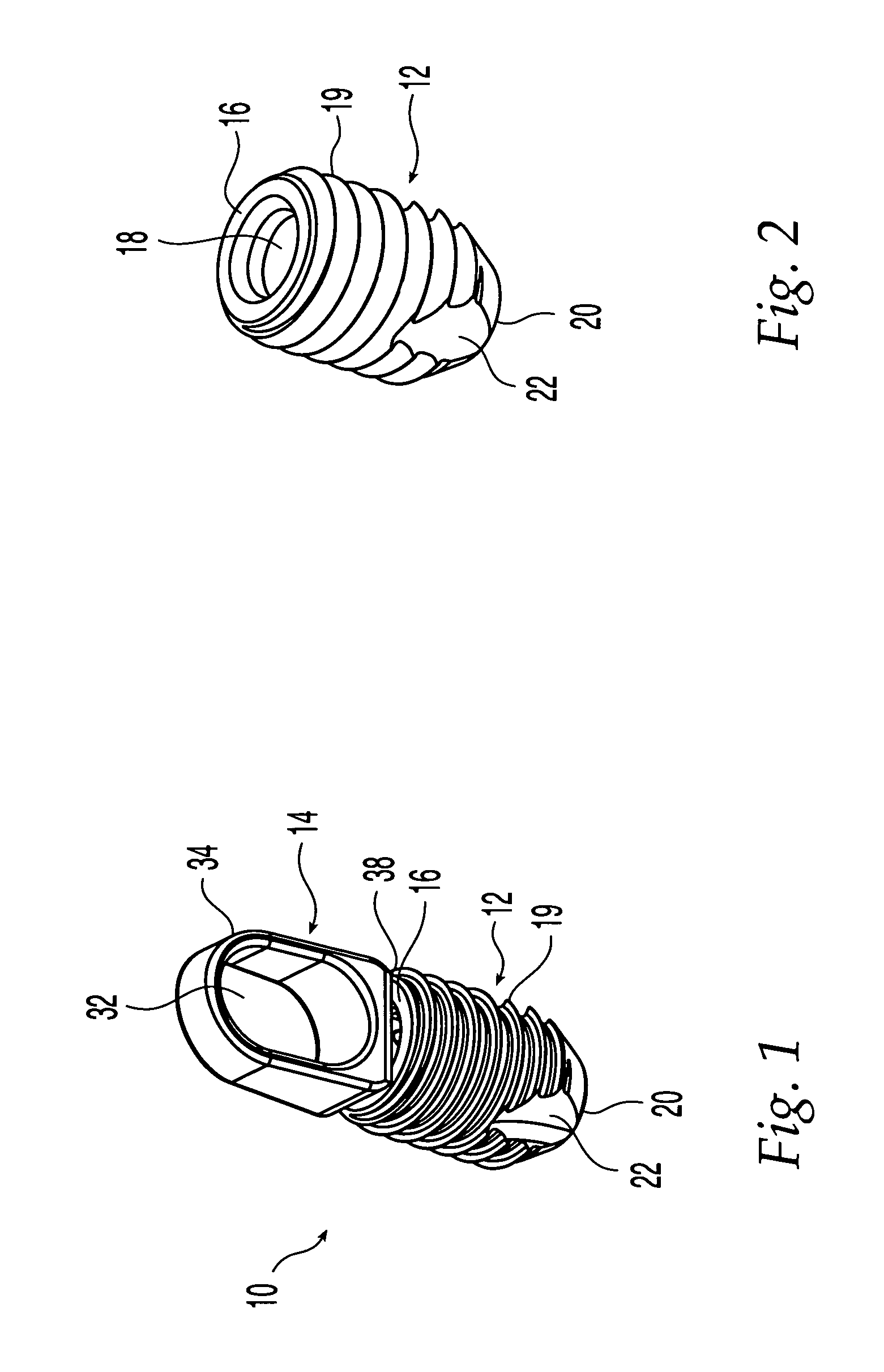
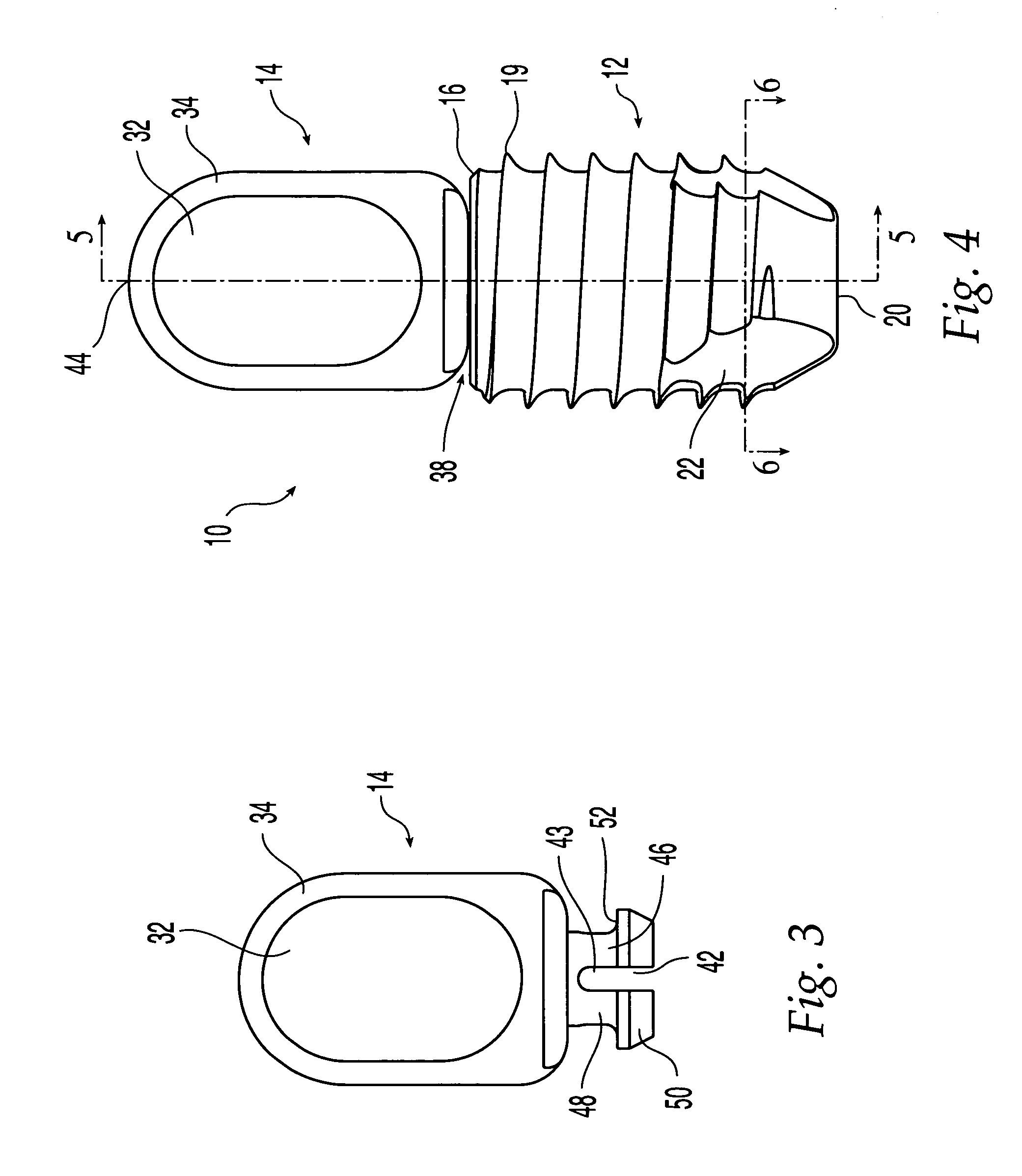
[0052]FIG. 1 illustrates a soft-tissue graft fixation device 10 according to an embodiment of the invention which may be used for implanting and affixing one end of a soft-tissue graft, such as, for example, a hamstring tendon graft, in a bone tunnel. Graft fixation device 10 includes body 12 and graft interface member 14 connected thereto.

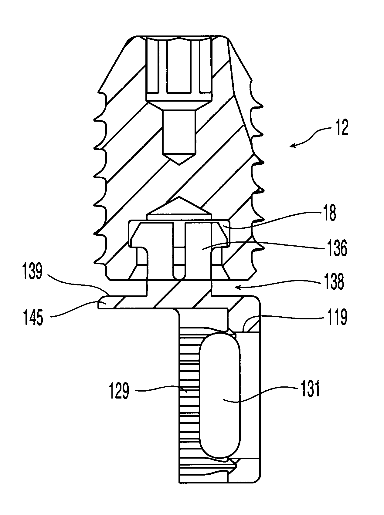
[0053]Body 12 (FIG. 2) is the portion of the graft fixation device that may be anchored directly in a prepared bone tunnel. Body 12 may also be connected directly to graft interface member 14 (FIG. 3) which holds the graft. Body 12 and graft interface member 14 may be connected to form a two-piece assembly prior to implantation in a bone tunnel which preferably forms an integral construct which is not readily separable into its component parts, as illustrated according to a preferred embodiment in FIGS. 4 and 5. A coupling end 16 of threaded body 12 has a recess 18 for rotatably receiving graft interface member 14, as described below. Because body...


PUM


Abstract

A graft fixation device, system and method are disclosed for reconstruction or replacement of a ligament or tendon preferably wherein a soft tissue graft or a bone-tendon-bone graft is received and implanted in a bone tunnel. The graft fixation system includes a fixation device comprising a threaded body which is rotatably connected to a graft interface member. One embodiment of the implant/graft interface member includes an enclosed loop for holding a soft tissue graft. Another embodiment of the interface member includes a bone cage comprising a cage bottom and removable cage top to hold a bone block at one end of a bone-tendon-bone (BTB) graft. An additional embodiment of the interface member includes a one-piece bone cage which may be crimped or stapled to a bone block. The fixation device holds a graft in centered axial alignment in a bone tunnel. The body portion of the fixation device may be turned without imparting substantial twist to a graft attached to the device, due to the rotatable coupling between the threaded body and the interface member. The fixation device may be installed using a driver tool that has a shaft and an outer sleeve, wherein the driver may be used to twist the fixation device and independently exert a pushing or pulling force thereto. The graft fixation method may be used to install a fixation device by pulling or pushing it into a prepared bone tunnel while minimizing the possibility of abrasion or other damage to a graft attached to the fixation device.

Description

FIELD OF THE INVENTION[0001]The present invention relates to a ligament or tendon reconstruction fixation system and a method for reconstruction or replacement of a ligament or tendon wherein a soft tissue graft or a bone-tendon-bone graft is received within a bone tunnel.BACKGROUND OF THE INVENTION[0002]In arthroscopic surgery, a torn or ruptured ligament or tendon may be treated by attaching an end of a tendon or ligament graft to bone. The graft end may be secured to the bone by any of a variety of devices and techniques. One common procedure, for example, involves the replacement of the anterior cruciate ligament (ACL) of the knee. In such operations, a tunnel is typically prepared through the patient's tibia, across the interarticular joint and into the femur. A hamstring tendon graft or a bone-tendon-bone graft may be attached to an implantable graft fixation device or screw or the like which is frequently planted in the femoral tunnel to help anchor one end of the graft there...

Claims


Application Information

Patent Timeline
Patent Type & Authority Patents(United States)
IPC IPC(8): A61B17/04A61F2/08
CPCA61F2/0805A61F2/0811A61F2002/0829A61F2002/0852A61F2002/0882
Inventor WILFORD, TROYCARTER, CORY W.
Owner AO TECH AG
Why Eureka
Try Eureka