Seal arrangement for residual limb prosthetic socket

a residual limb and prosthetic socket technology, applied in the field of hermitic seal arrangements, can solve the problem of requiring a comparatively large prestressing for

Active Publication Date: 2006-12-05
KAUPTHING BANK
View PDF69 Cites 98 Cited by
  • Summary
  • Abstract
  • Description
  • Claims
  • Application Information

AI Technical Summary

Benefits of technology

[0013]Accordingly, the objective of the present invention is to create a seal the se

Problems solved by technology

It is observed that a comparatively large prestressing force is required, which in turn may entail interfer

Method used


Image

  • Seal arrangement for residual limb prosthetic socket
  • Seal arrangement for residual limb prosthetic socket
  • Seal arrangement for residual limb prosthetic socket

Examples


Embodiment Construction

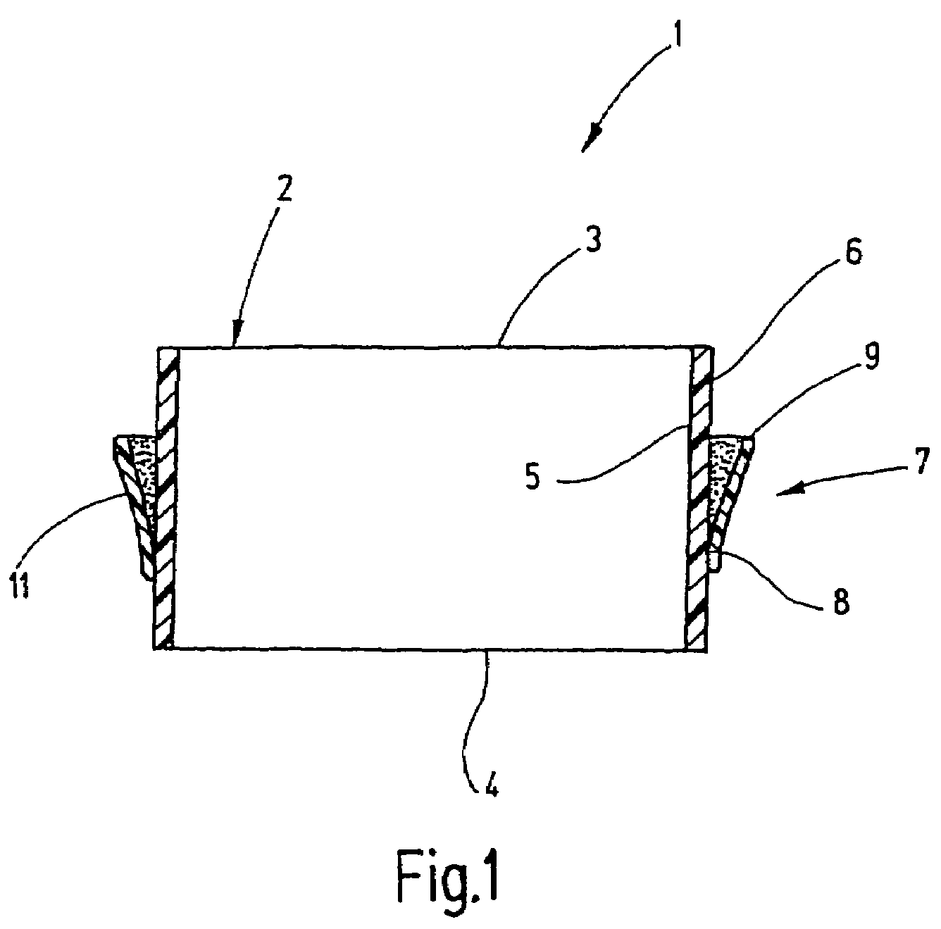
[0038]In a schematic manner, FIG. 1 shows a seal 1 designed to seal off a residual limb (not shown) relative to the inside volume of a prosthetic socket (not shown) for the purpose of keeping the socket against the residual limb by means of a partial vacuum, i.e. to enhance its affixation to the residual limb.

[0039]The seal 1 comprises a cuff-like base 2 having a proximal end face 3, a distal end face 4, and an inside surface 5 and an outside surface 6.

[0040]The cuff-like base is tubular in the broadest sense and is formed of an air tight, elastically stretchable material. The diameter of said base 2 is selected in a manner that it may be properly seated on a residual limb while being very minimally prestressed. A peripheral sealing lip 7 is affixed on the outside surface 6 of the base 2 and comprises a root 8 and a sealing edge 9 extending at least in part diagonally away from said root. The sealing lip 7 also is shaped like an annulus peripherally surrounding the outside surface 6...


PUM


Abstract

A prosthetic socket seal includes at least one radially projecting sealing lip which jointly with a base subtends an annular gap. This annular gap is vented on a proximal side by the external atmosphere, resulting in creation of a pressure gradient at the sealing lip that produces stronger compression of the sealing lip against the prosthetic socket with increasing partial vacuum on a distal side of the sealing lip.

Description

BACKGROUND OF THE INVENTION[0001]A. Field[0002]This invention relates to hermitic seal arrangements between residual limbs and vacuum retained prosthetic sockets.[0003]B. Related Art[0004]Residual limbs of amputees are inserted like a piston in a cup-shaped prosthetic sockets. Thus, it is known to utilize atmospheric air pressure (or partial vacuum) to retain such prosthetic sockets on residual limbs. A residual limb for this purpose must be kept hermetically sealed against the inner prosthetic socket wall or against a liner pulled over the residual limb.[0005]With proper sealing, a force tending to remove the prosthetic socket from the residual limb will generate a partial vacuum that reacts against the force. On the other hand the retention force collapses immediately when air enters a gap between the residual limb and the prosthetic socket.[0006]The European patent application EP 0 632 765 discloses a prosthetic socket fitted with a seal which maintains sealing between the residu...

Claims


Application Information

Patent Timeline
IPC IPC(8): A61F2/80A61F2/00A61F2/50A61F2/76A61F2/78
CPCA61F2/80A61F2002/5009A61F2002/7806A61F2002/7818A61F2002/802A61F2210/009A61F2250/0024
Inventor CARSTENS, FELIX
Owner KAUPTHING BANK
Why Eureka
Try Eureka