Imprint method and device
a technology of imprinting and printing method, applied in the field of imprinting process and device, can solve the problems of high consumption of pressure medium, difficult to make it compatible with clean rooms, and limit the cycle tim
- Summary
- Abstract
- Description
- Claims
- Application Information
AI Technical Summary
Benefits of technology
Problems solved by technology
Method used
Image
Examples
first embodiment
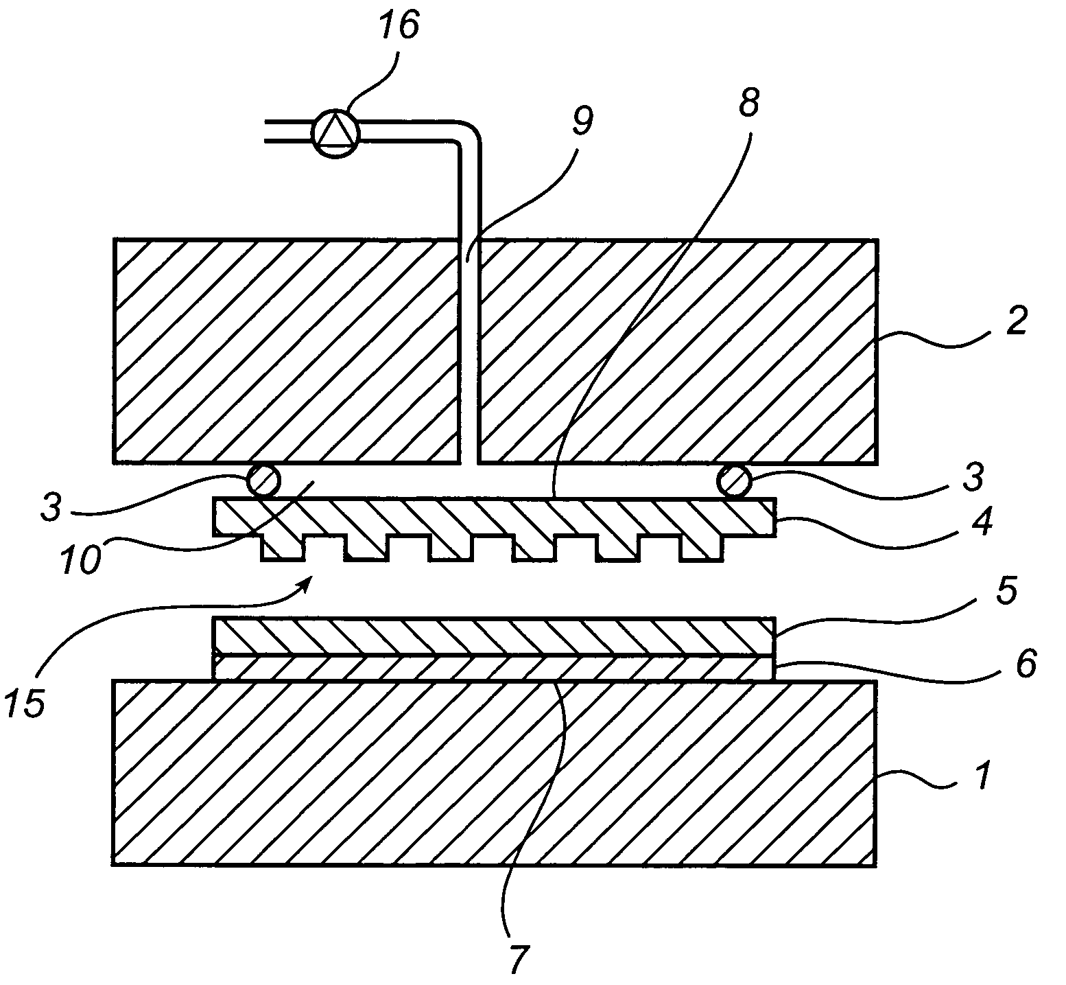
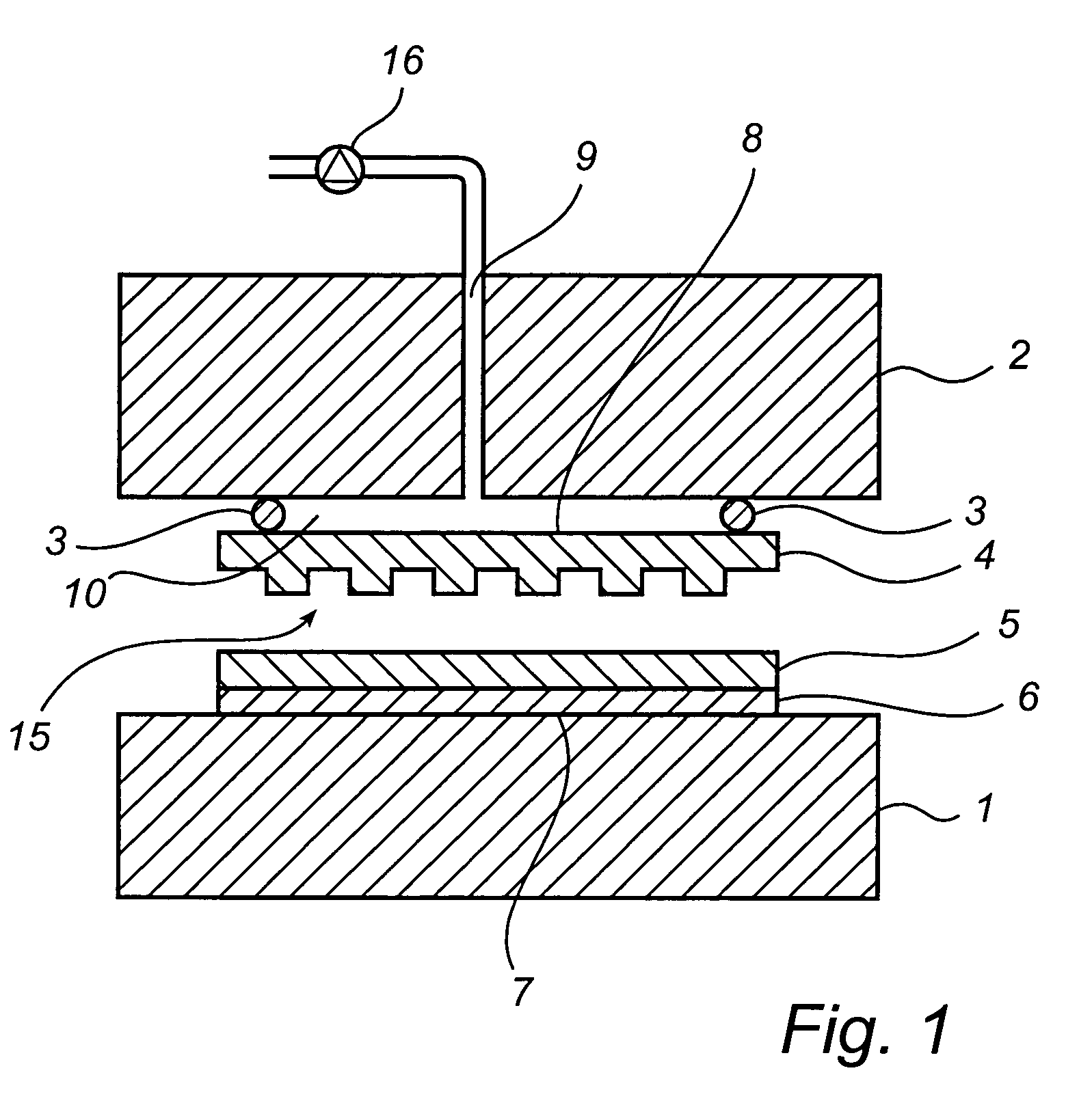
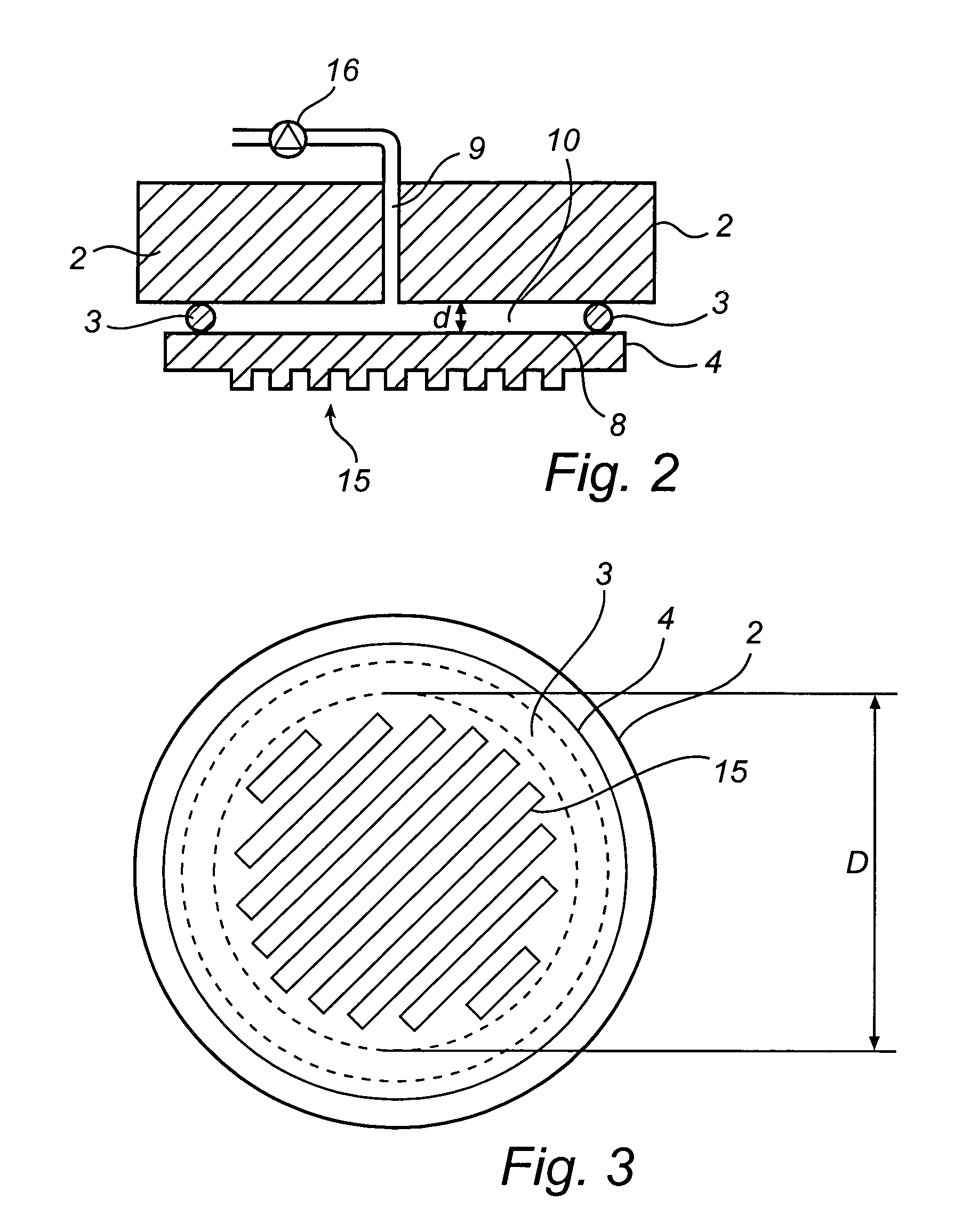
[0050]FIG. 1 is a schematic cross sectional view of the invention. In FIG. 1, a first support member 1, and a second support member 2 are arranged to support a substrate 6 and a template 4, respectively. The substrate 6 and the template 4 may be sheet-like structures, i.e. having two major surfaces and a relatively thin cross section. At least one of the major surfaces is the active surface, i.e. the surface having the relief pattern in the case of the template and the surface having the moldable film, in the case of the substrate. The thickness of the template and the substrate may be constant, but it may also vary, as long as the active surfaces remain essentially plane.
[0051]The support members 1, 2 may be movable relative each other in order to enable the insertion and removal of the substrate 6 and the template 4. In the embodiment shown in the enclosed drawings, the substrate is arranged horizontally on a lower support member 1, while the template is arranged horizontally on a...
second embodiment
[0063]FIG. 4 is a schematic cross sectional of the invention The embodiment of FIG. 2 essentially corresponds to the embodiment shown in FIG. 1, except for the addition of a recess 11 in the surface of the support member 2. The recess functions so as to increase the distance d between the surface of the support member 2 and the template back surface 8, Thus, the pressure cavity is defined by the template back surface 6, the sealing gasket 3 and the recess. It is realized that the recess does not need to have a uniform depth, but may have any suitable shape. Also, the recess may cover a surface area that is equal to the area provided with the relief pattern, or a smaller area. It may be provided with e.g. grooves for controlling airflows within the cavity.
third embodiment
[0064]FIG. 5 is a schematic cross sectional view of the invention, wherein multiple, in this case two sealing gaskets 3, 13 are arranged between the template and the surface of the second support member 2. This embodiment is particularly suitable when the substrate and / or the template has a through hole, such as is the case with e.g. compact discs (CD) or digital versatile discs (DVD).
[0065]In this embodiment, the pressure cavity is defined by the surface of the support member 2, the template back surface and the two sealing gaskets 3, 13. Thus the pressure is provided only in the area where the relief pattern 15 is situated, and there is no pressure provided in the area where the hole is. This enables processing of templates and / or substrates having a through hole, without losing pressure. This may also prevent the template from being damaged by the contact with the edges of the holes.
[0066]Also in this embodiment, it is possible to provide a recess in the support member 2 surface,...
PUM
| Property | Measurement | Unit |
|---|---|---|
| height | aaaaa | aaaaa |
| height | aaaaa | aaaaa |
| height | aaaaa | aaaaa |
Abstract
Description
Claims
Application Information
 - R&D
- Intellectual Property
- Life Sciences
- Materials
- Tech Scout
- Unparalleled Data Quality
- Higher Quality Content
- 60% Fewer Hallucinations
Browse by: Latest US Patents, China's latest patents, Technical Efficacy Thesaurus, Application Domain, Technology Topic, Popular Technical Reports.
© 2025 PatSnap. All rights reserved.Legal|Privacy policy|Modern Slavery Act Transparency Statement|Sitemap|About US| Contact US: help@patsnap.com


